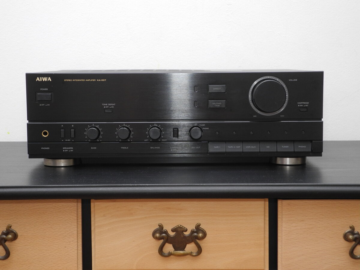
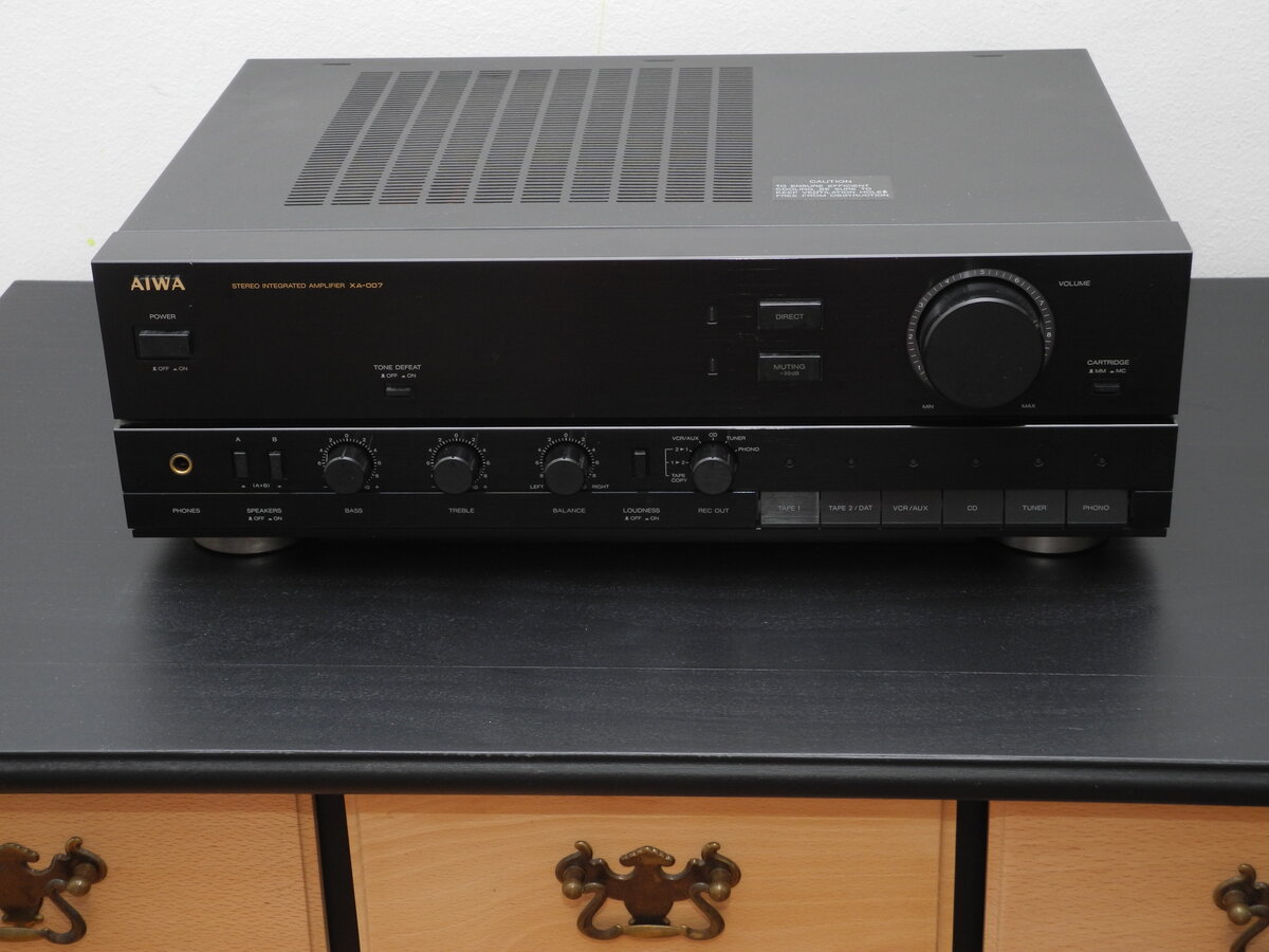
Aiwa XA-007
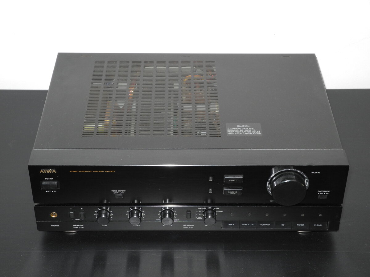
The Aiwa XA-007 is a stereo integrated amplifier produced in the early 1990s. It reflects Aiwa's classic approach to versatile and reliable hi-fi design.
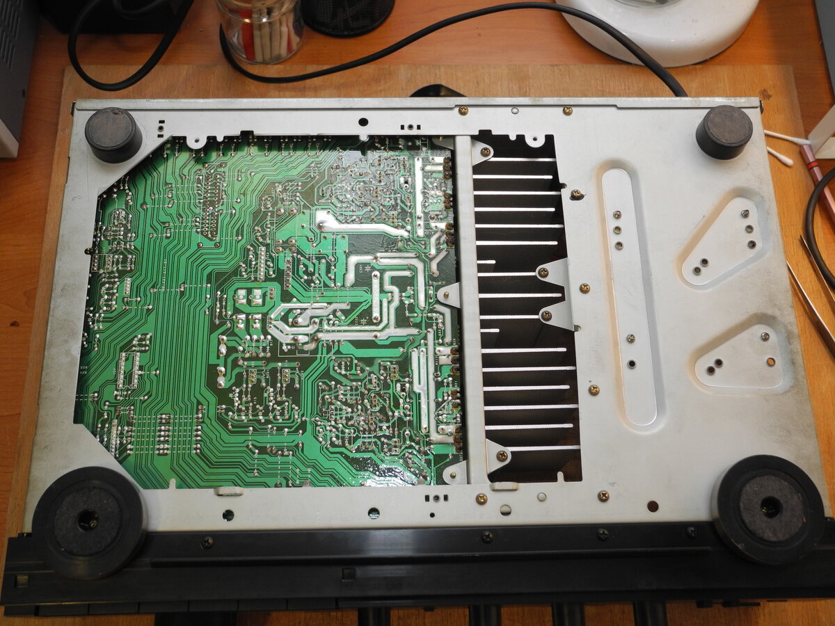
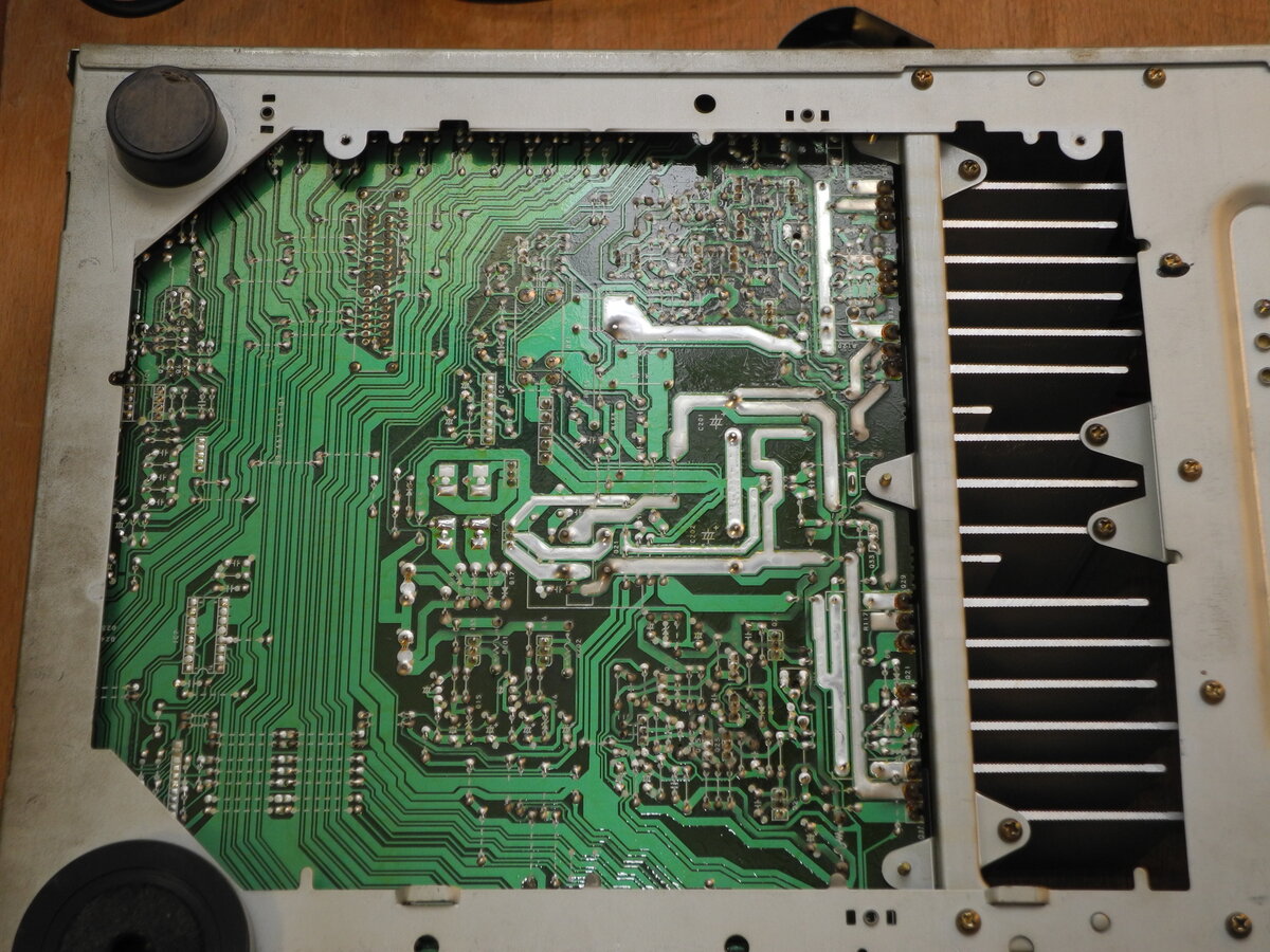
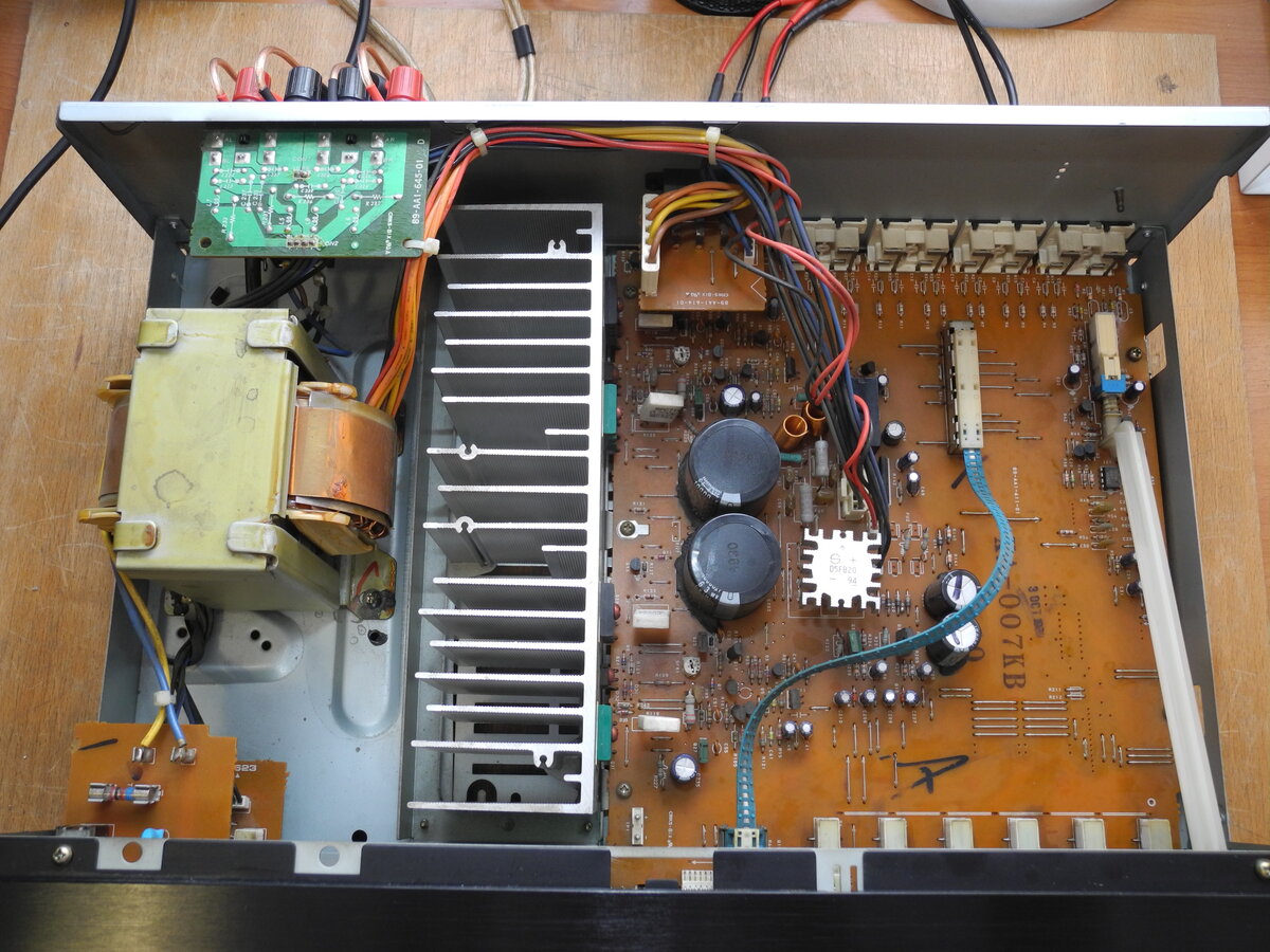
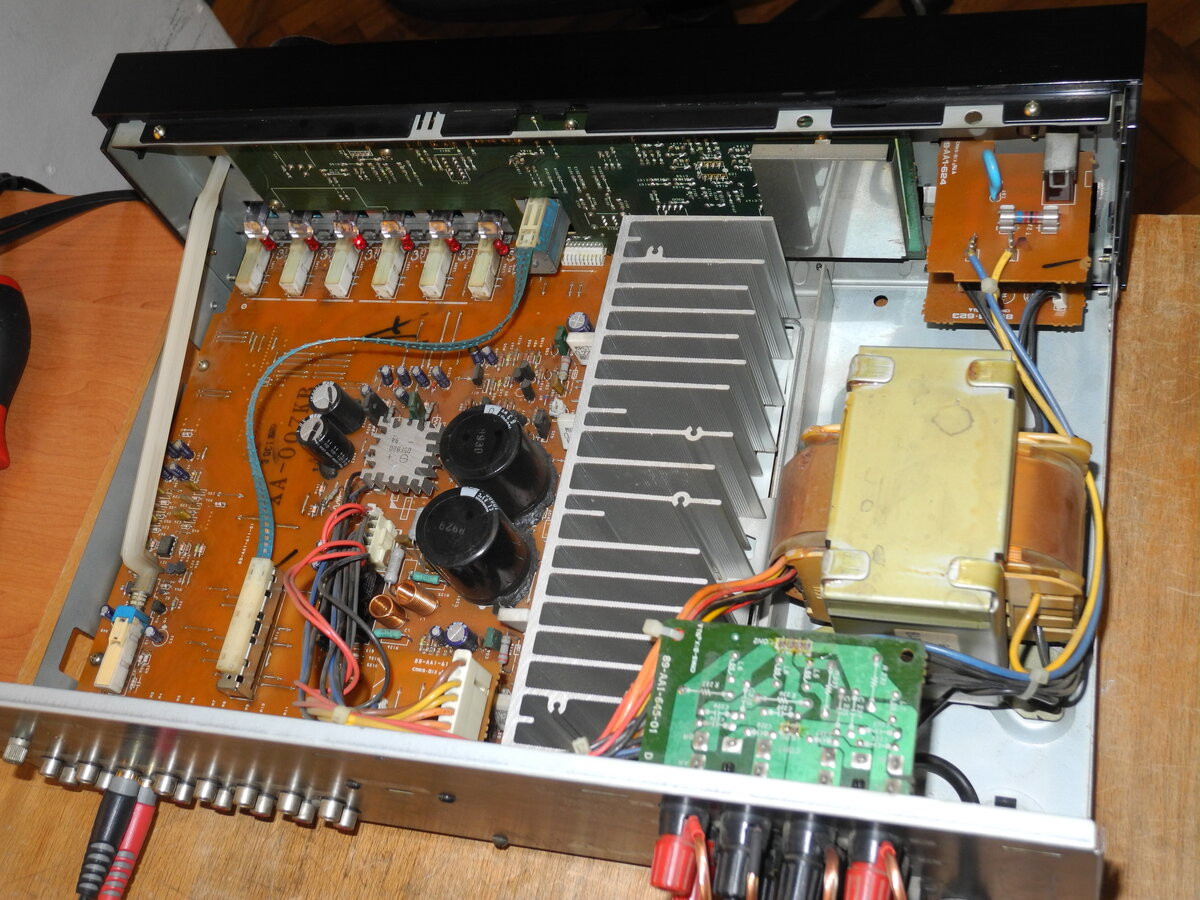
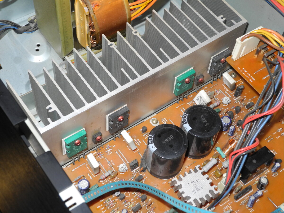
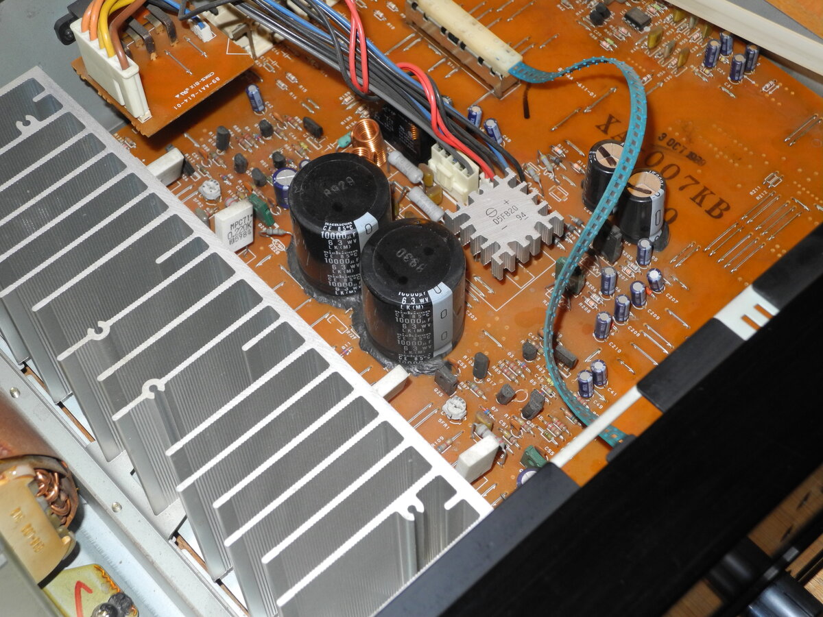
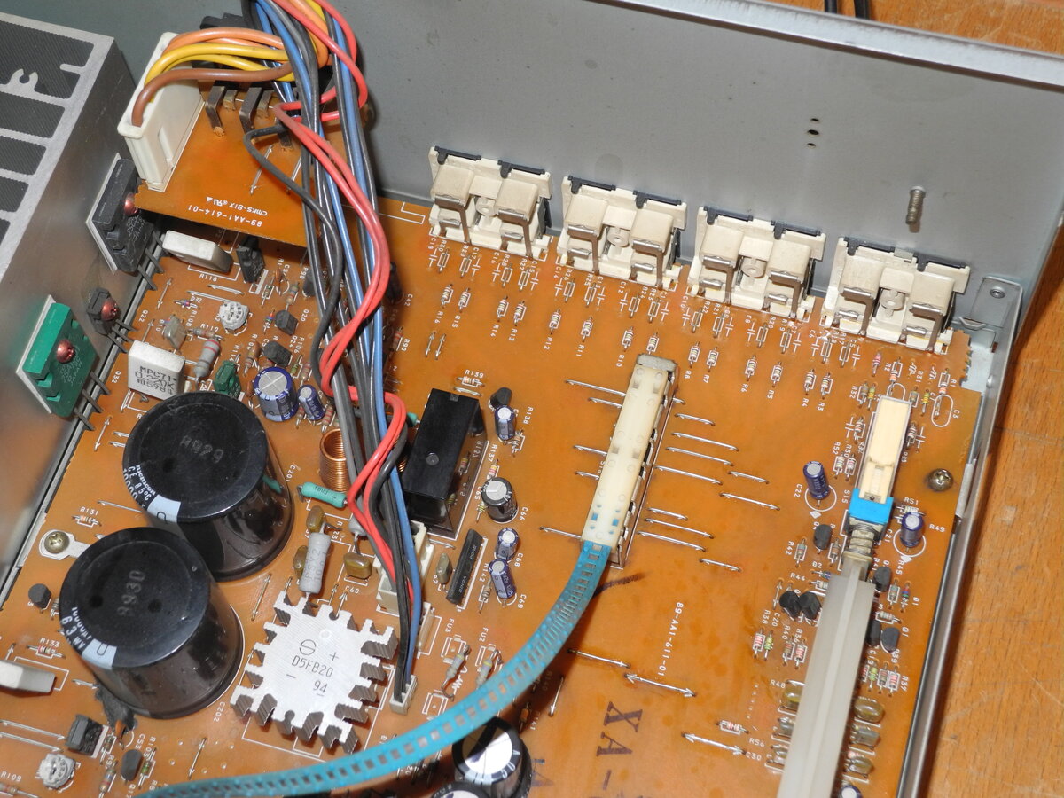
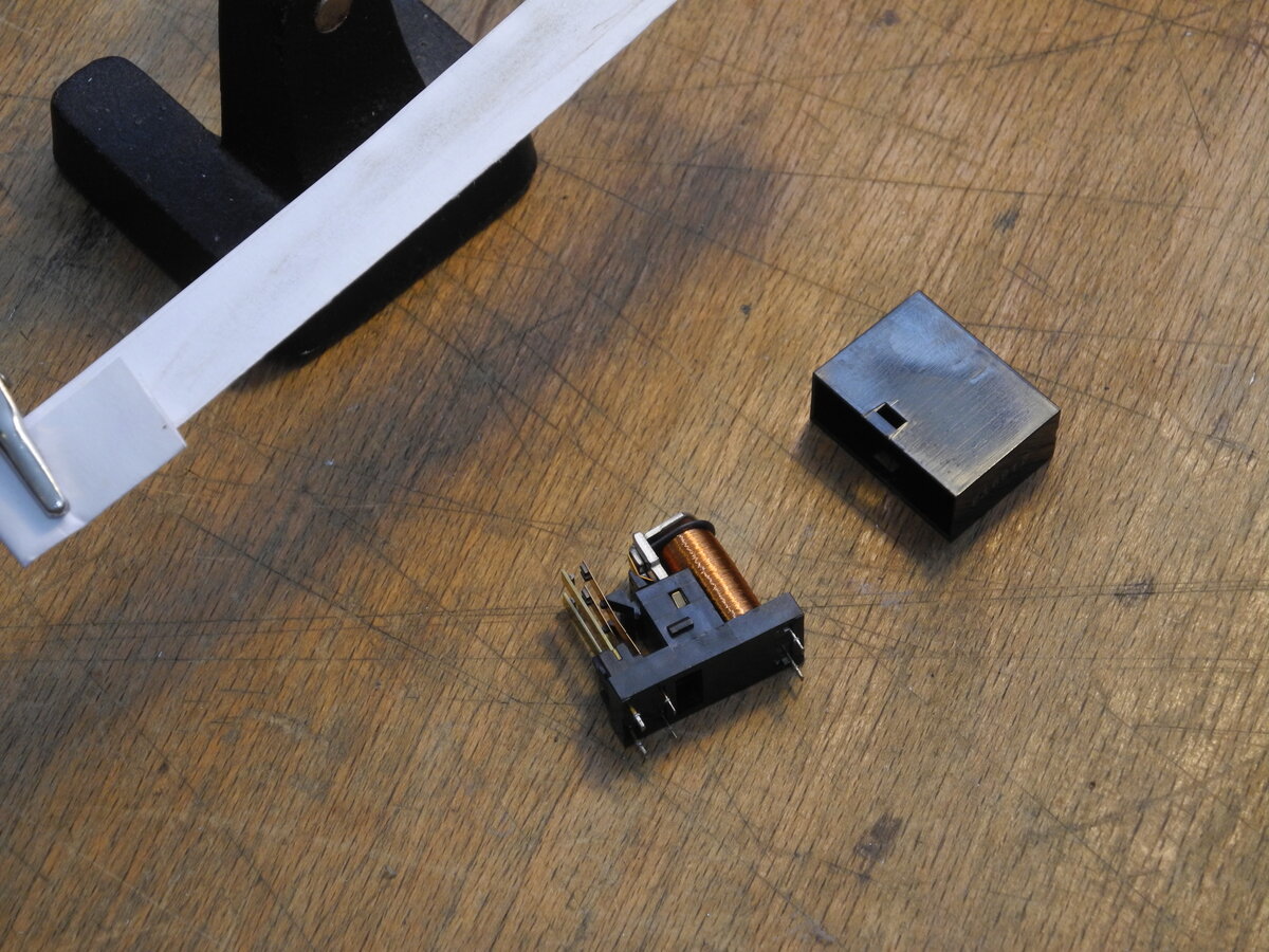
The power supply uses two 10000µF filter capacitors, providing a stable energy reserve. The output stage is built around large Toshiba 2SC3280 and 2SA1301 transistors. Speaker protection is handled by a relay controlled by the µPC1237 IC.
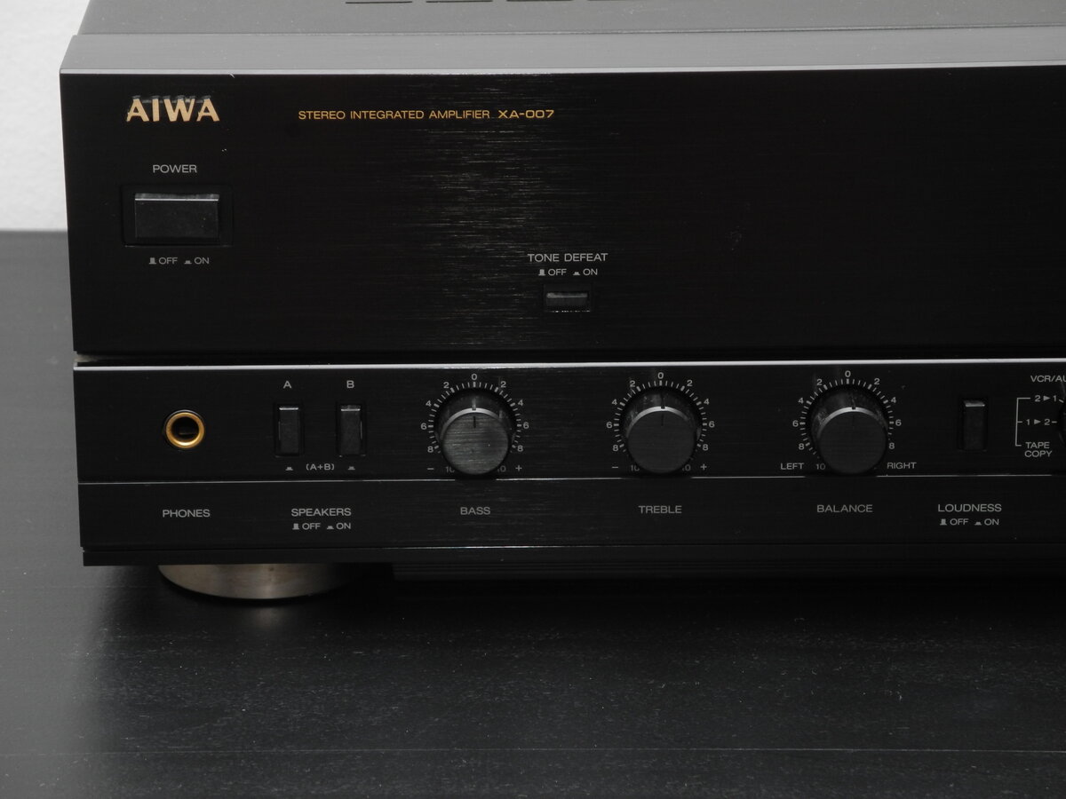
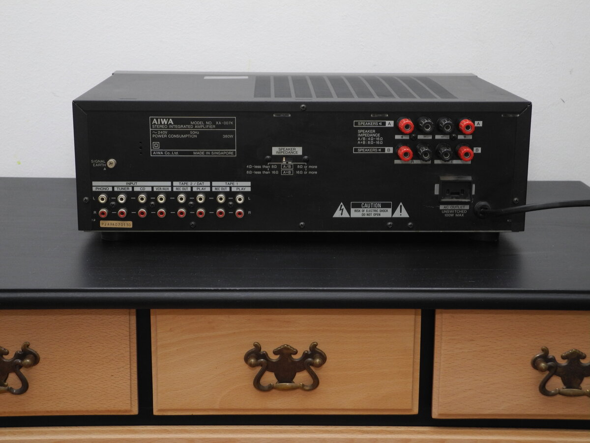
Connectivity is versatile, allowing the XA-007 to integrate easily into both vintage and modern systems. It features a classic Loudness option, while Tone Defeat and Direct modes are included for a cleaner signal path. The phono preamplifier offers MM/MC support for different cartridge types.
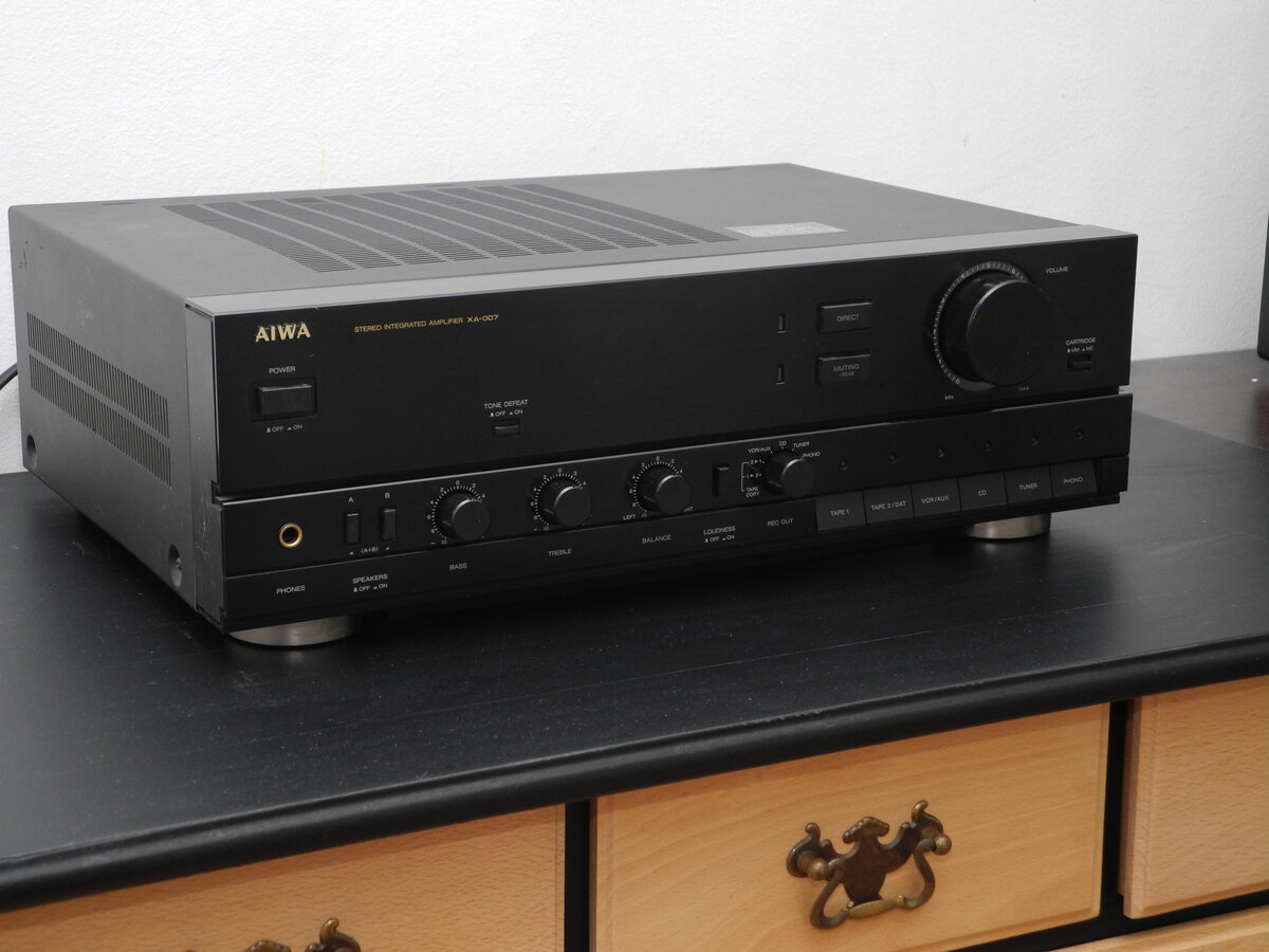
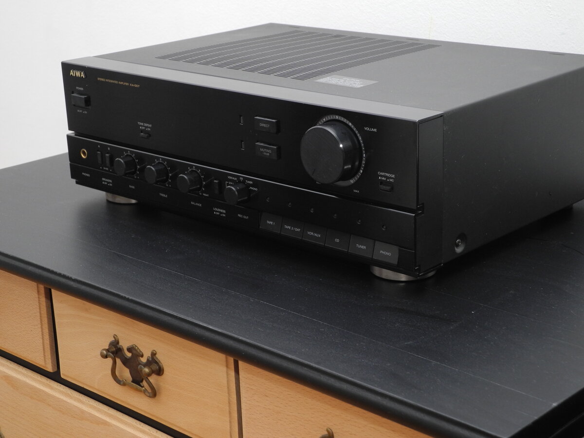
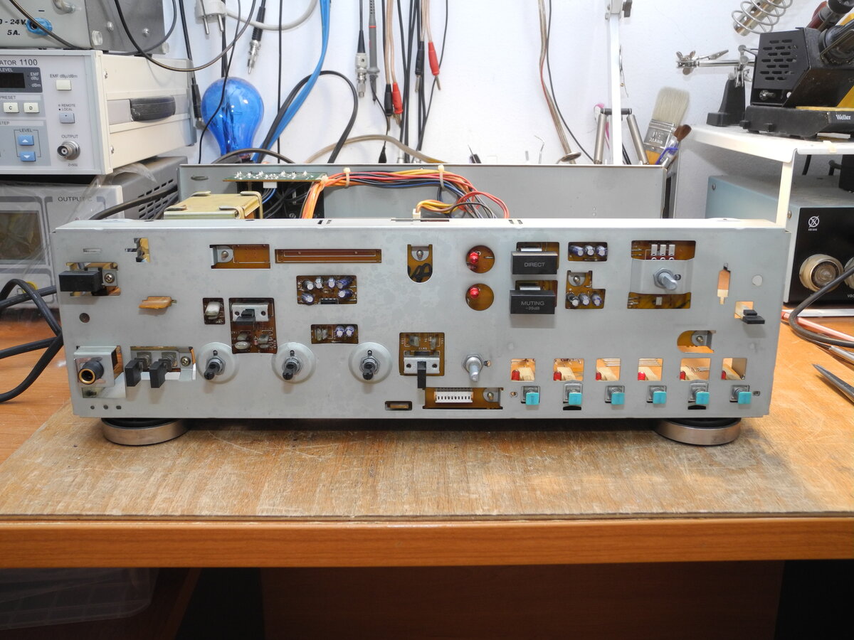
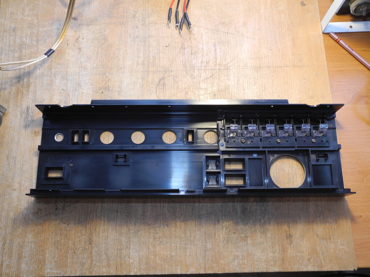
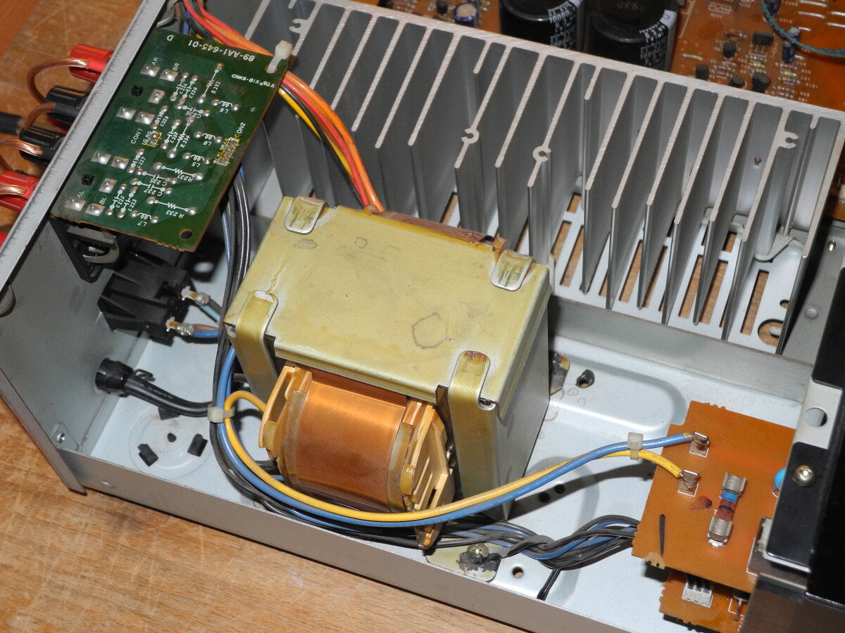
Finished with a black faceplate and a straightforward, functional layout, the XA-007 maintains a traditional hi-fi aesthetic while focusing on usability and dependable performance. The chassis construction is typical of its era, and internal components are accessible for service and maintenance.
Manufacturer: Aiwa
Status: Defunct company
Source: Wikipedia (Aiwa)
General Specifications
Maximum power (8Ω): 80WFrequency response (5Hz-100kHz): 0,-3dB
Frequency response (20Hz-20kHz): <0.05%
THD (80W, 4-8Ω): 0.9%
THD (65W, 8Ω): 0.007%
Signal to noise ratio (Line): 105dB
Signal to noise ratio (MM): 94dB
Signal to noise ratio (MC): 75dB
Speaker load impedance: 4Ω-16Ω
Dimensions (WHD): 430×140×335mm
Weight: 8.4kg
Produced: 1989-1992
Initial price: 700DM
Measured Values
Maximum power (8Ω): 84WFrequency response (20Hz-20kHz): <1.0dB
Channel imbalance: <0.2dB
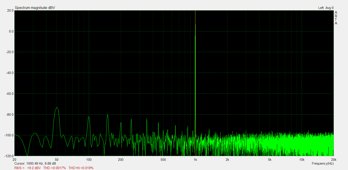
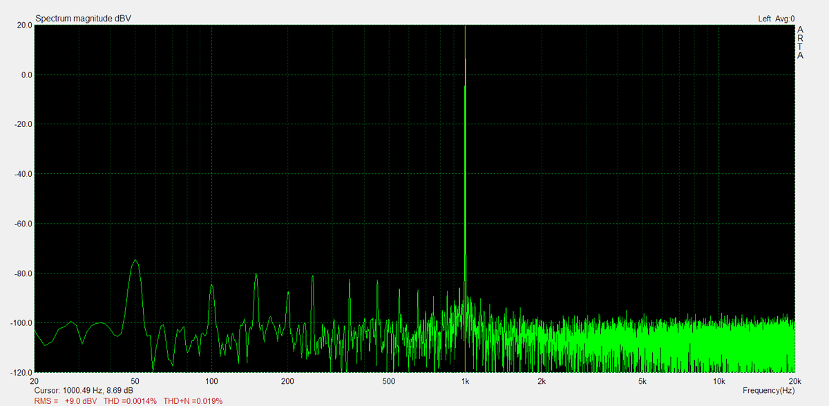
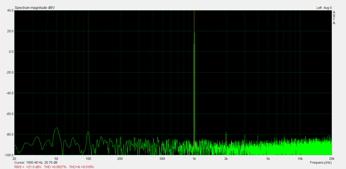
THD (1kHz, 1W): 0.0017%
THD+N (1kHz, 1W): 0.019%
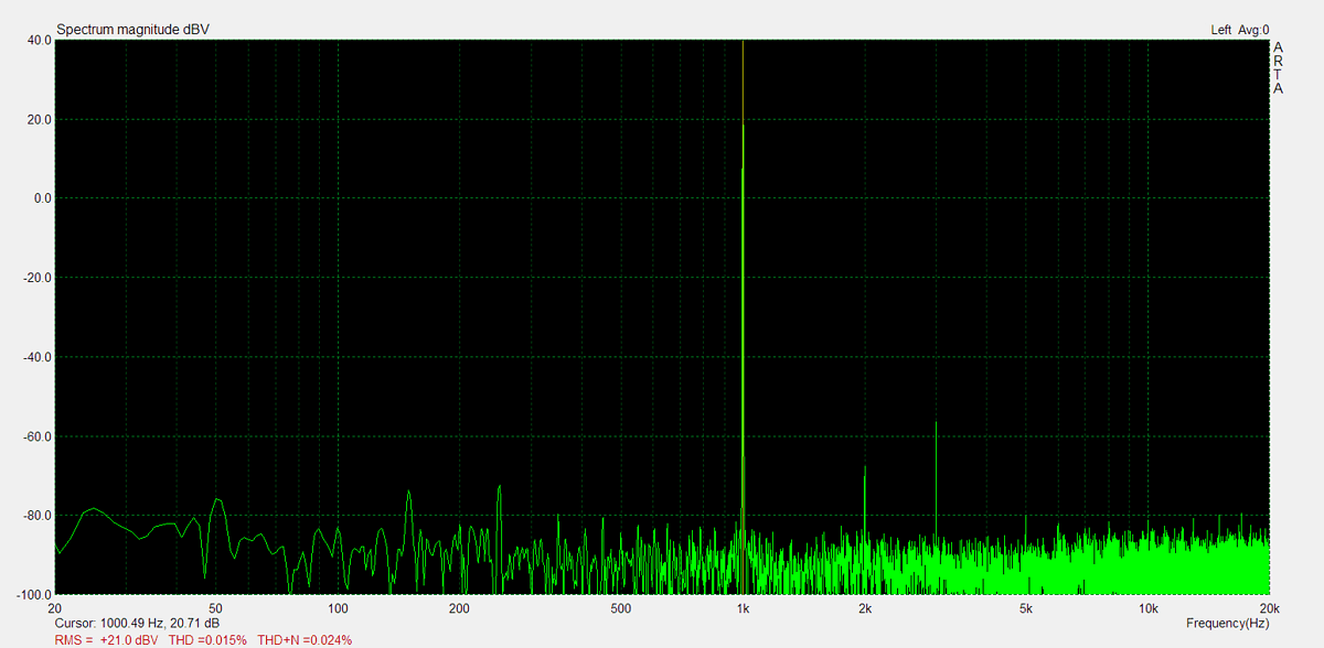
THD (1kHz, 20W): 0.015%
THD+N (1kHz, 20W): 0.024%
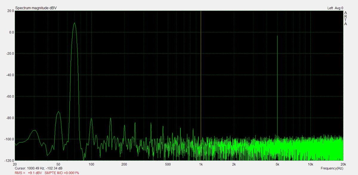
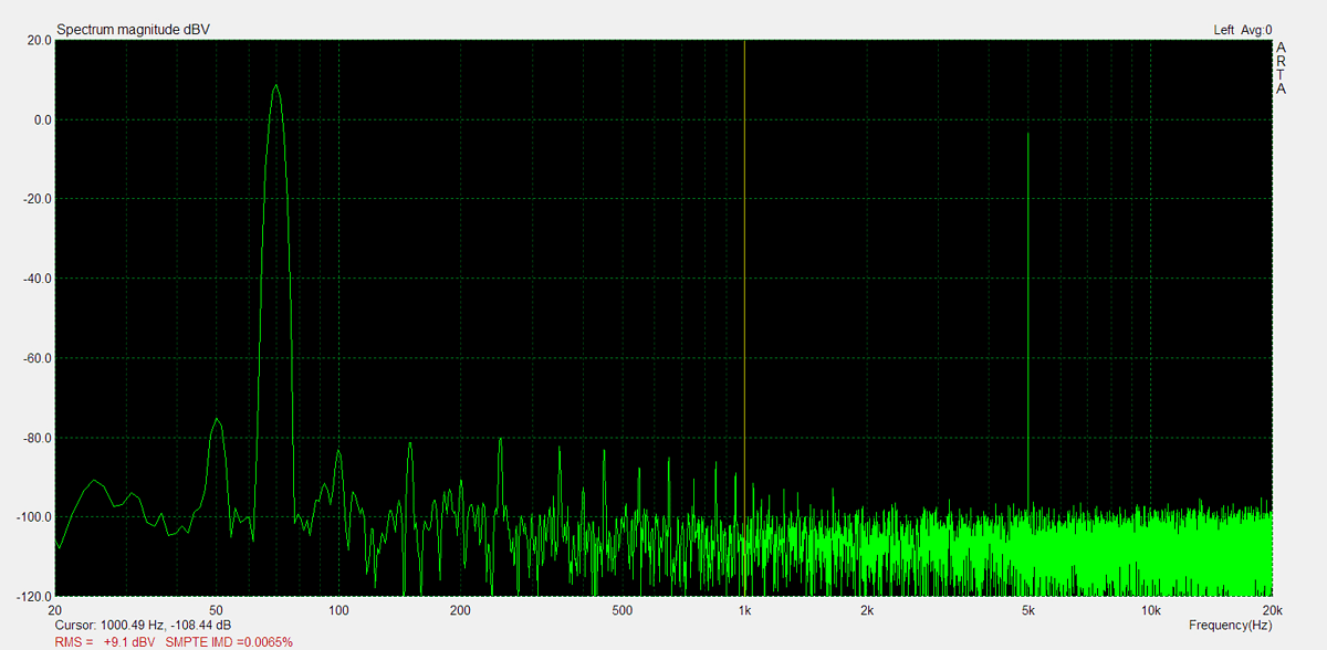
IMD (70Hz, 5kHz, 1W): 0.0065%
Noise: -67.8dB
Amplification (Line): 172.8
DC offset L: 1.5mV
DC offset R: 3.3mV
Factory Specification Sheet
Factory specification images are sourced directly from the device's original service manual or user manual. These documents are produced by the manufacturer and provide authoritative information on the product's specifications.
Maximum Power
Maximum power is measured using 8Ω resistors on both channels. A 1kHz sine wave input signal is applied and gradually increased until higher harmonics rise significantly. Typically, this is the point at which output clipping occurs.
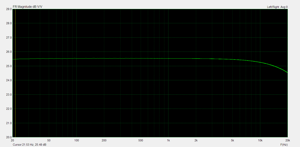
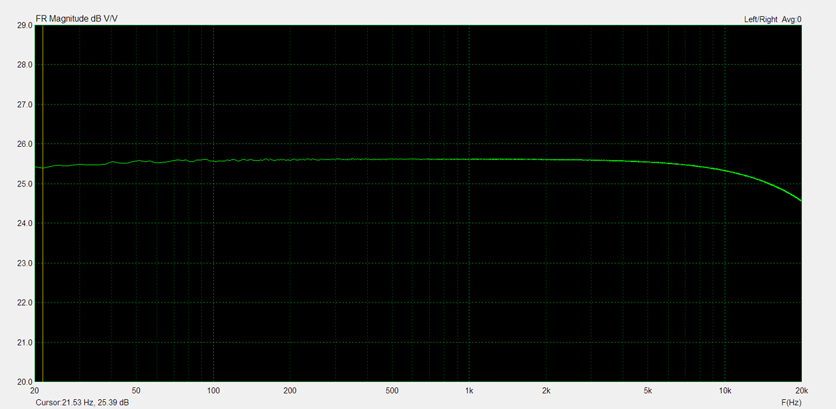
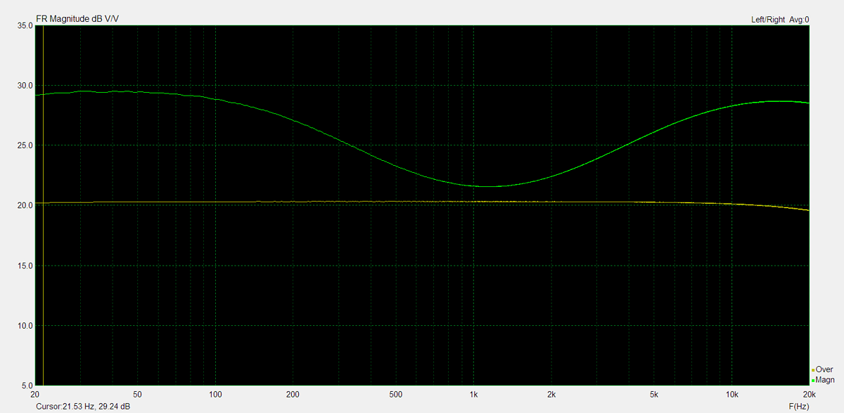
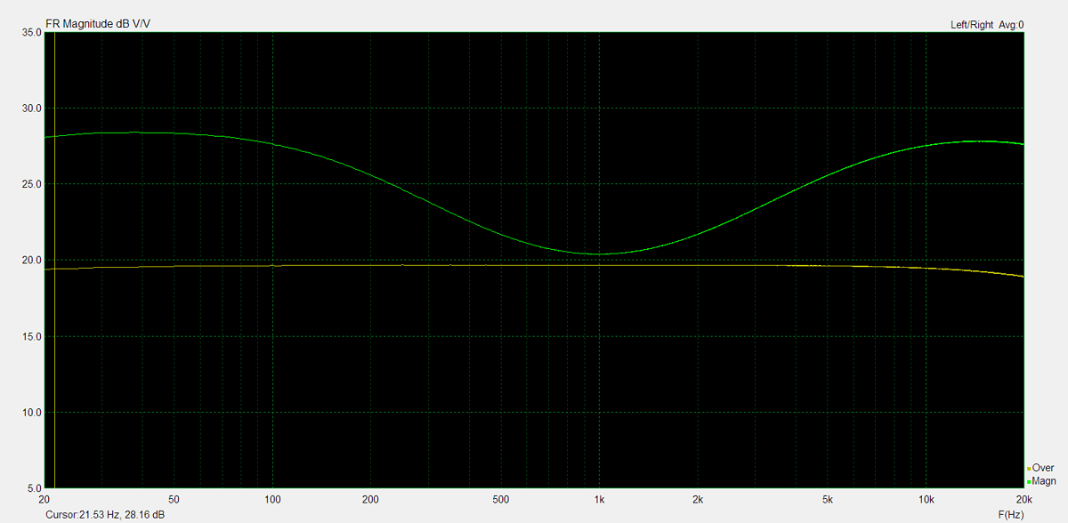
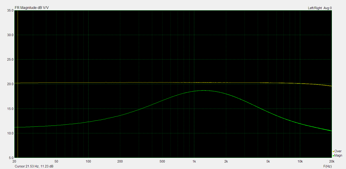
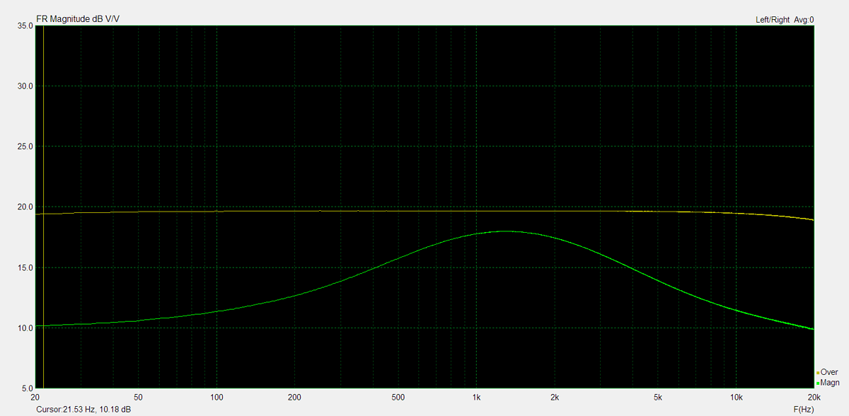
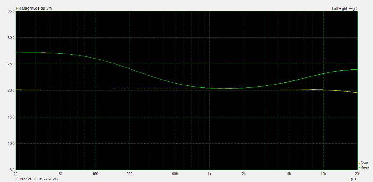
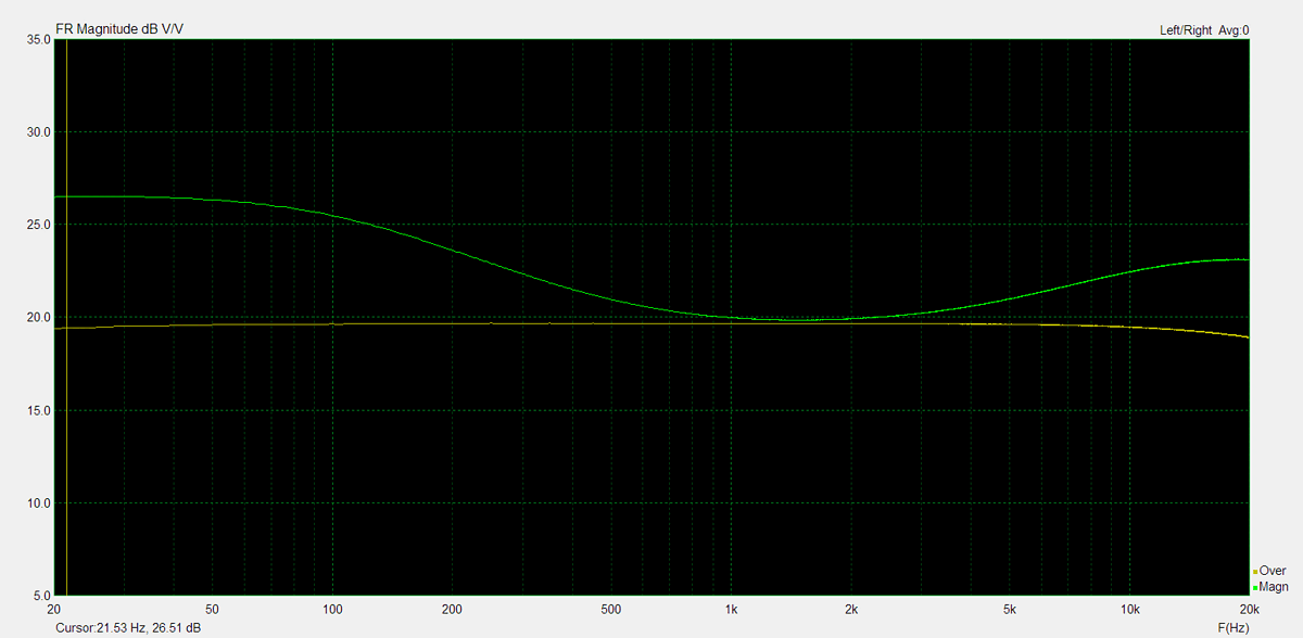
Frequency Response
Frequency response is measured using several equilizer settings. 'Flat' indicates the tone controls are either turned off or set to their neutral position. 'Max' and 'Min' refer to the maximum and minimum tone control positions, respectively. In the phono section, the expected response follows the RIAA equalization curve.
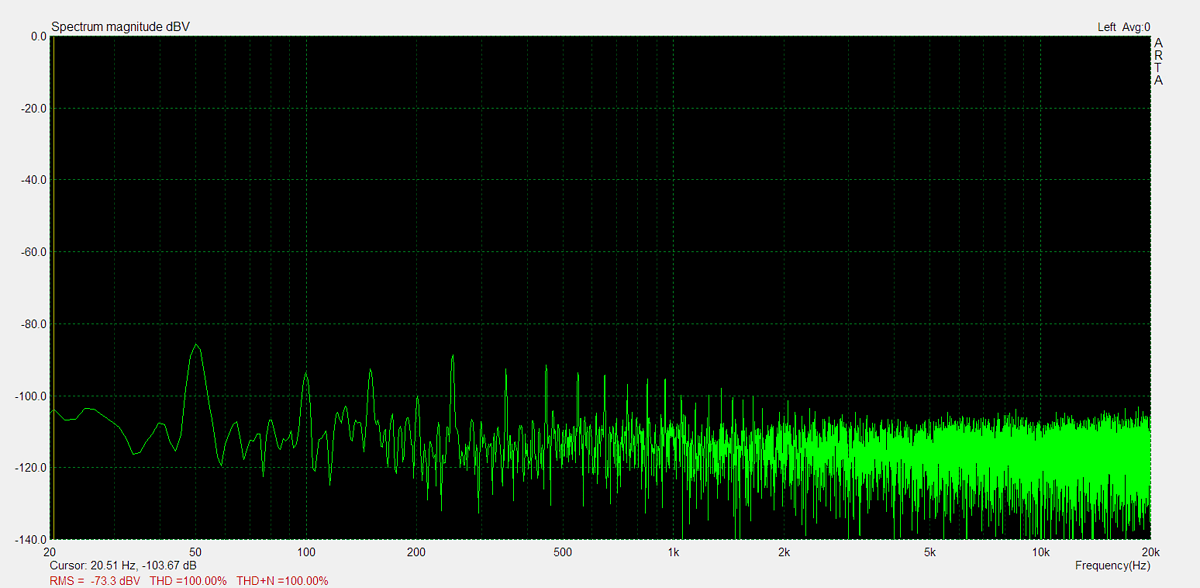
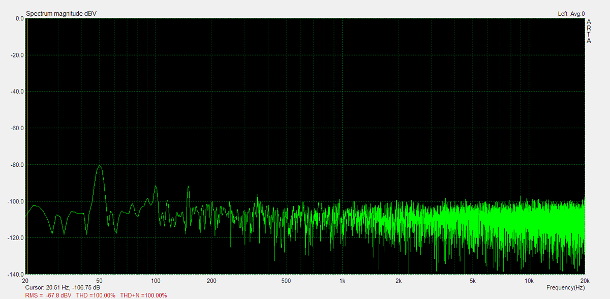
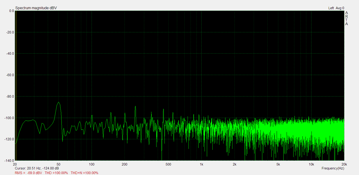
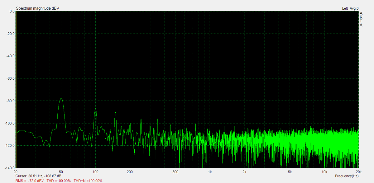
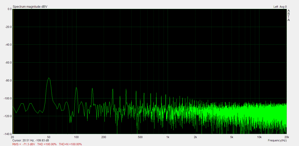
Residual Noise
These graphs display the noise levels at various volume positions. To eliminate any interference from the input signal, the input lines are shorted during the measurement. Generally, the noise is highest at the mid-point of the volume range (50%)

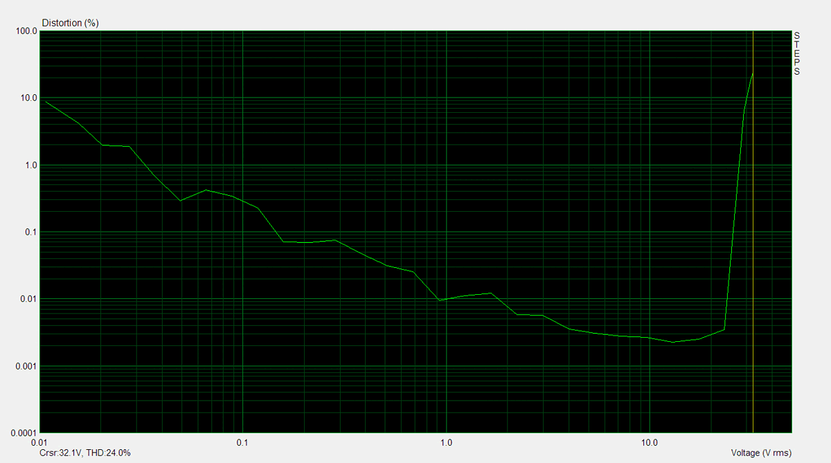
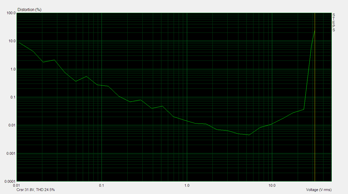
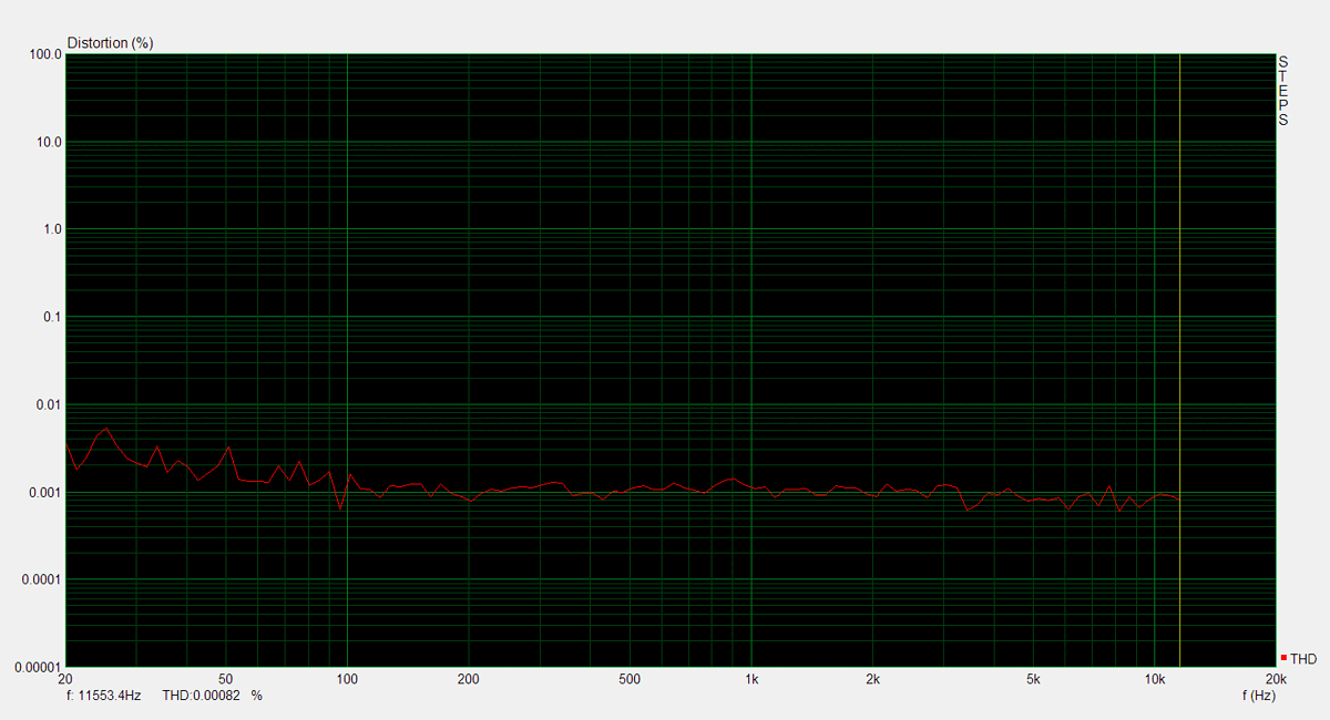
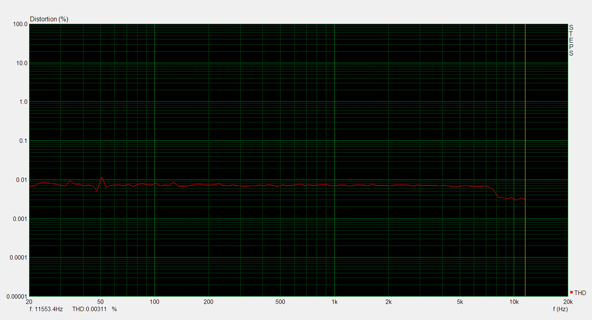
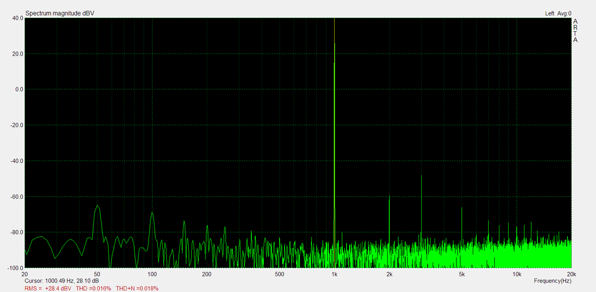
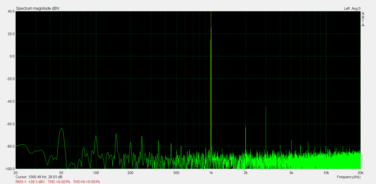
Distorsion
Total harmonic distortion (THD) is measured using a 1kHz sine wave input, with the output level adjusted to meet different conditions. Intermodulation distortion (IMD) is measured using 'two sine' input signal. THD versus voltage is measured with a 1kHz sine wave input, while THD versus frequency is measured at various output levels.