Thomson PA 5008E
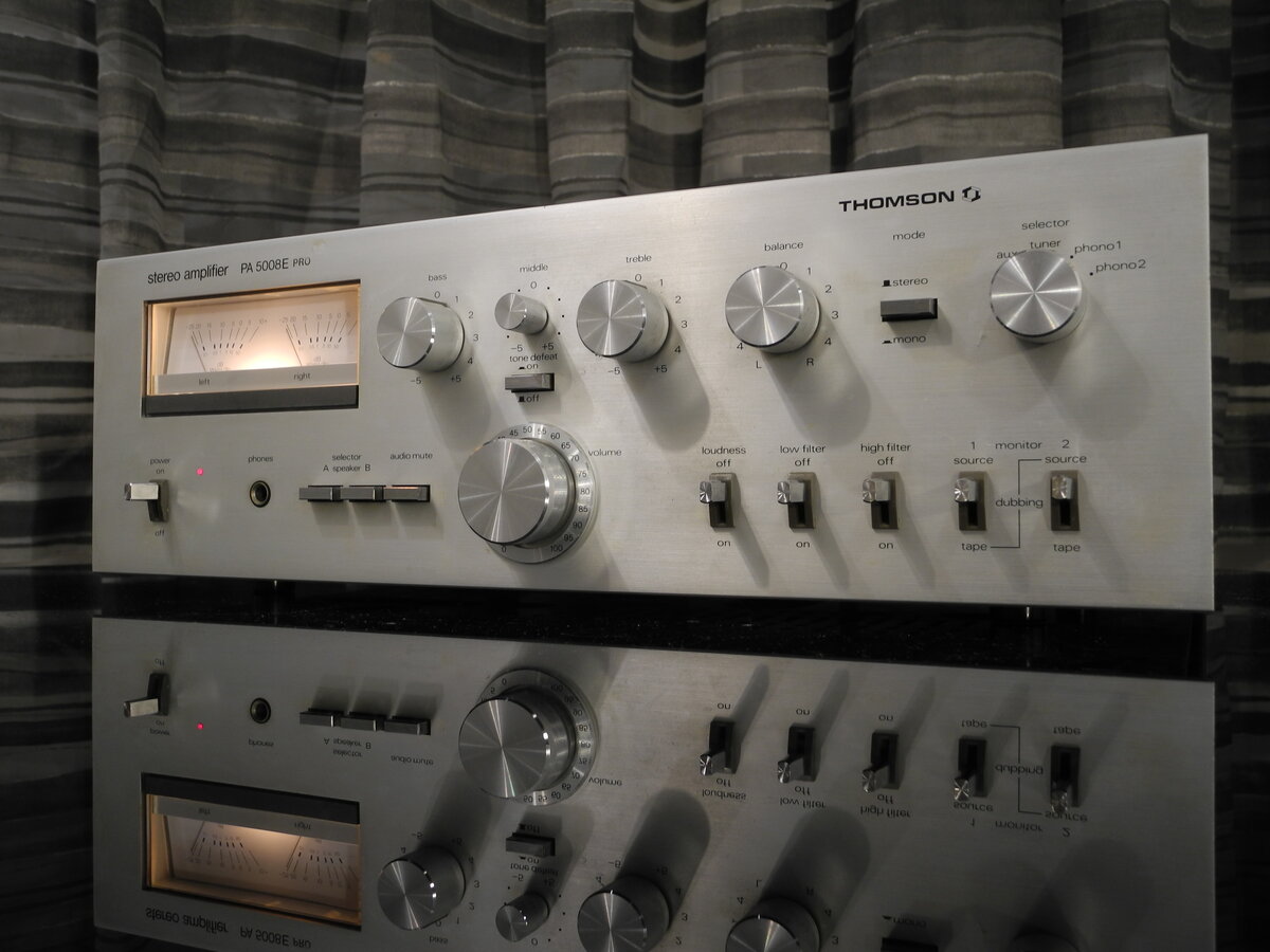
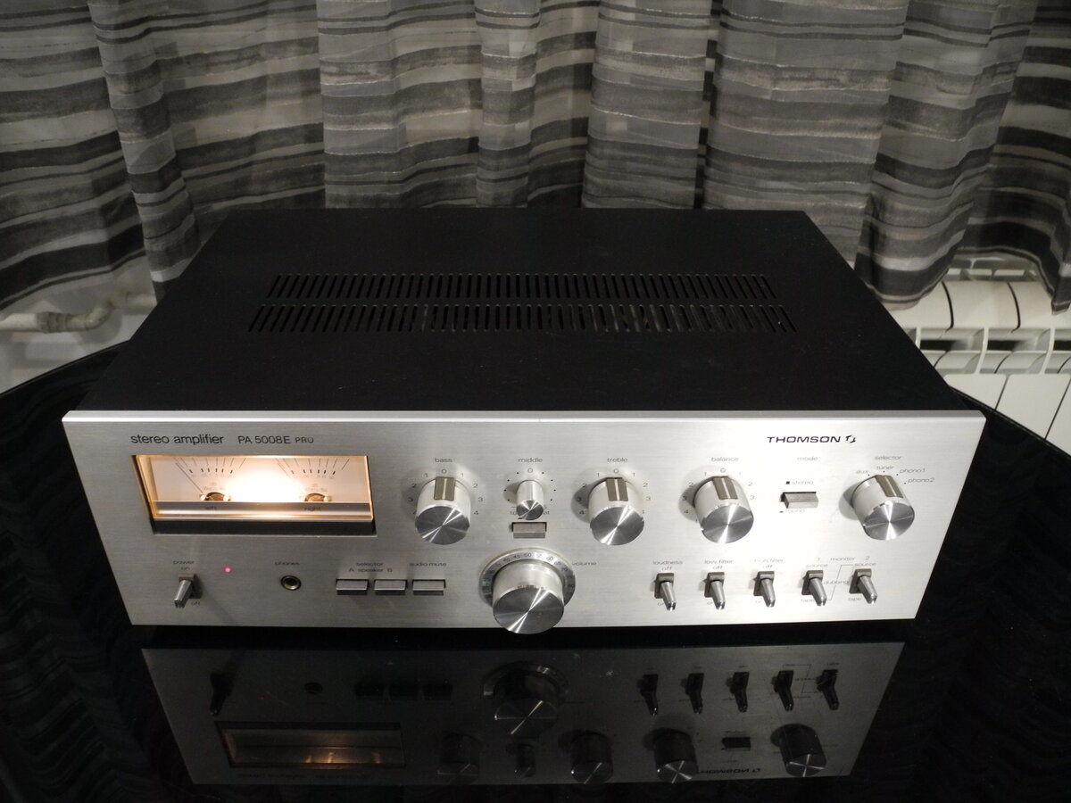
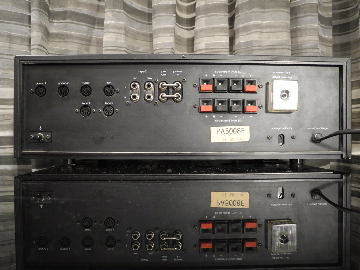
The Thomson PA 5008E is a vintage integrated stereo amplifier, probably from the late 1970s. Unfortunately, there are no related documents available online.
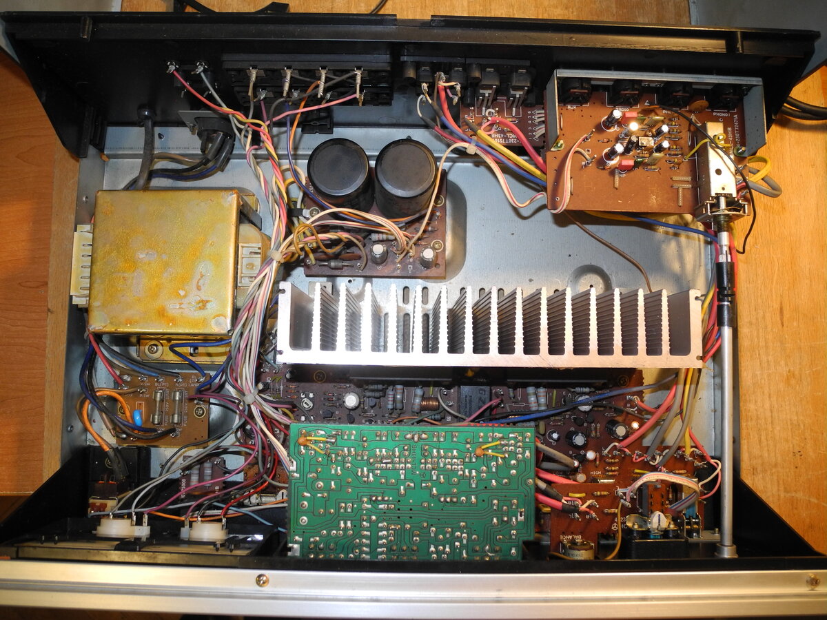
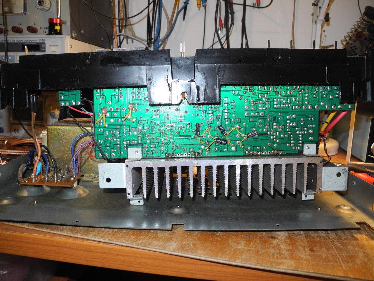
The output stage uses two STK049 hybrid power amplifier modules, with fairly large 8000µF capacitors in the power supply. Speaker outputs are protected by a relay.
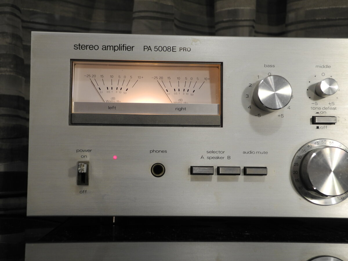
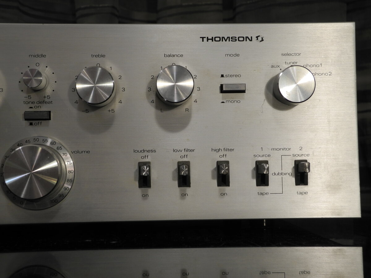
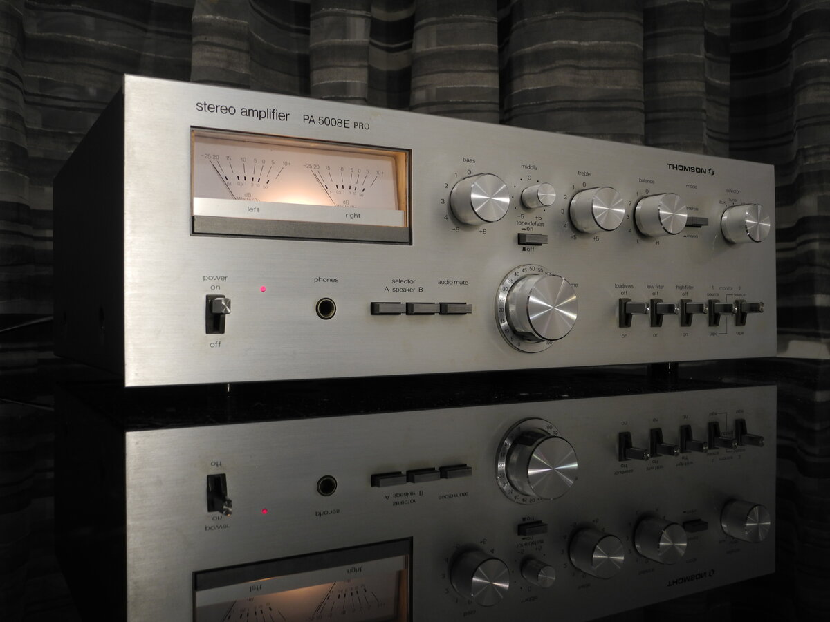
The front panel is made of brushed aluminium and features nice, massive knobs. In addition to two VU meters, the amplifier offers a good range of controls, including tone defeat, midrange equalizer, loudness, and low and high filters. The overall build quality is decent, with the chassis partially made of plastic.
Manufacturer: Thomson
Status: Defunct company
Source: Wikipedia (Thomson)

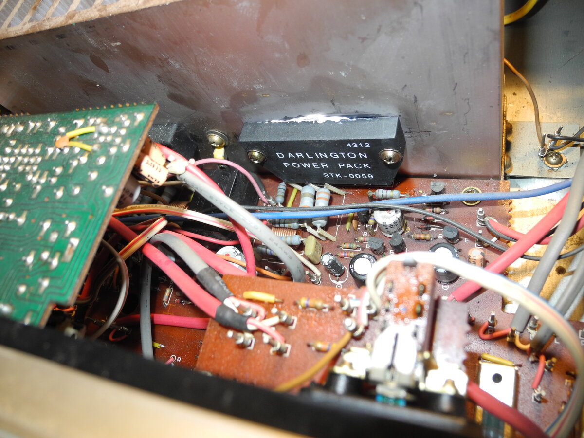
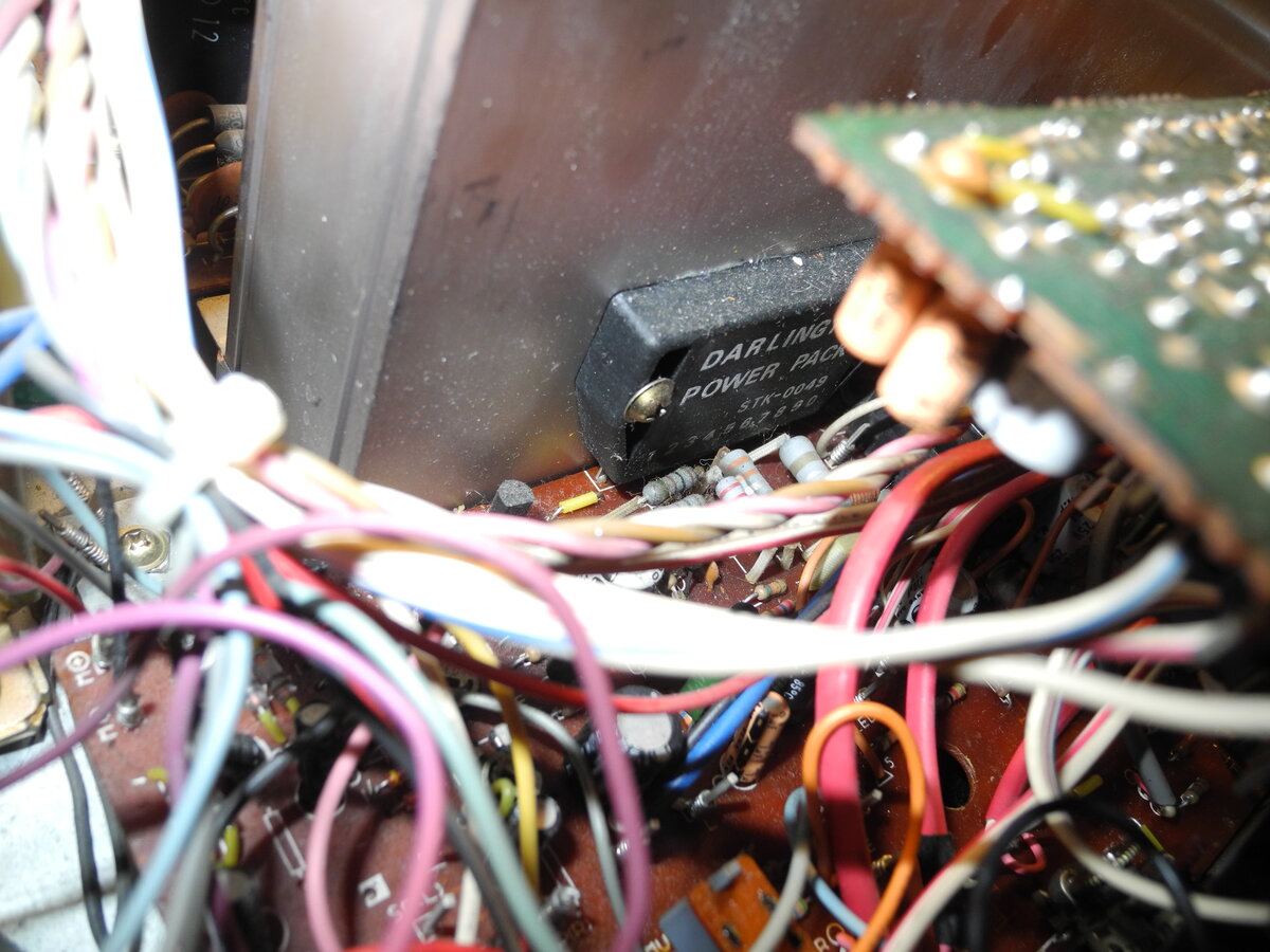
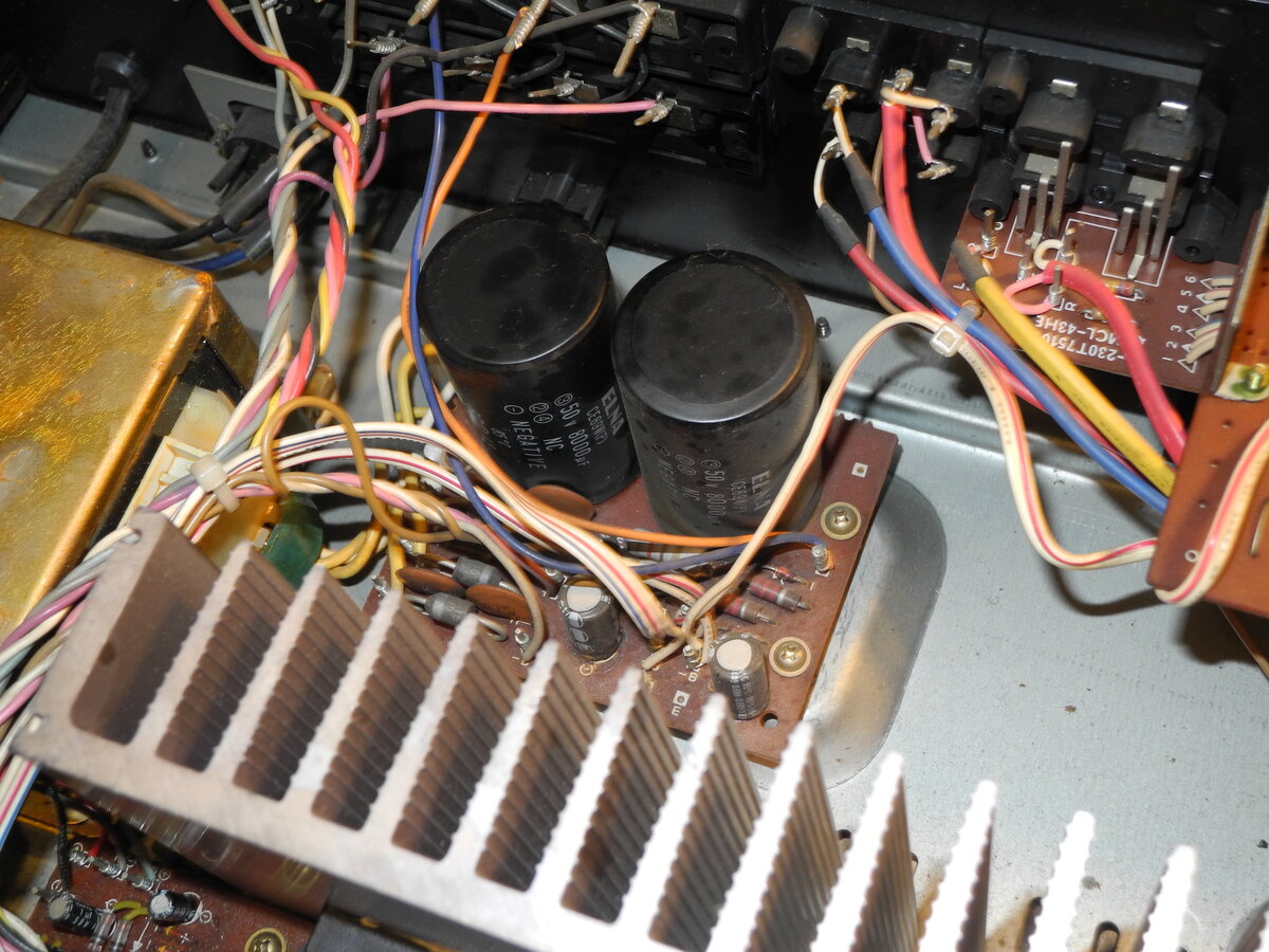
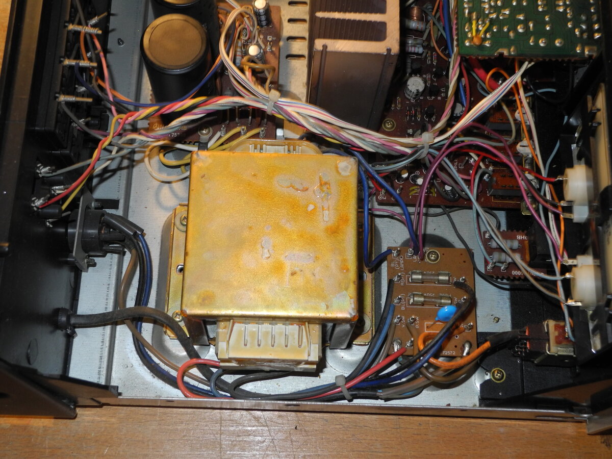
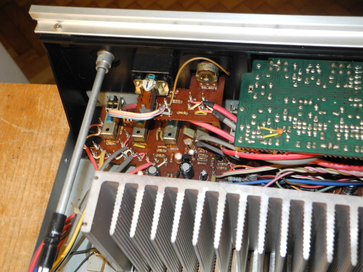

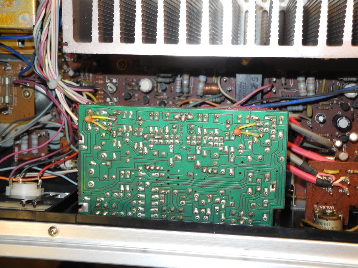
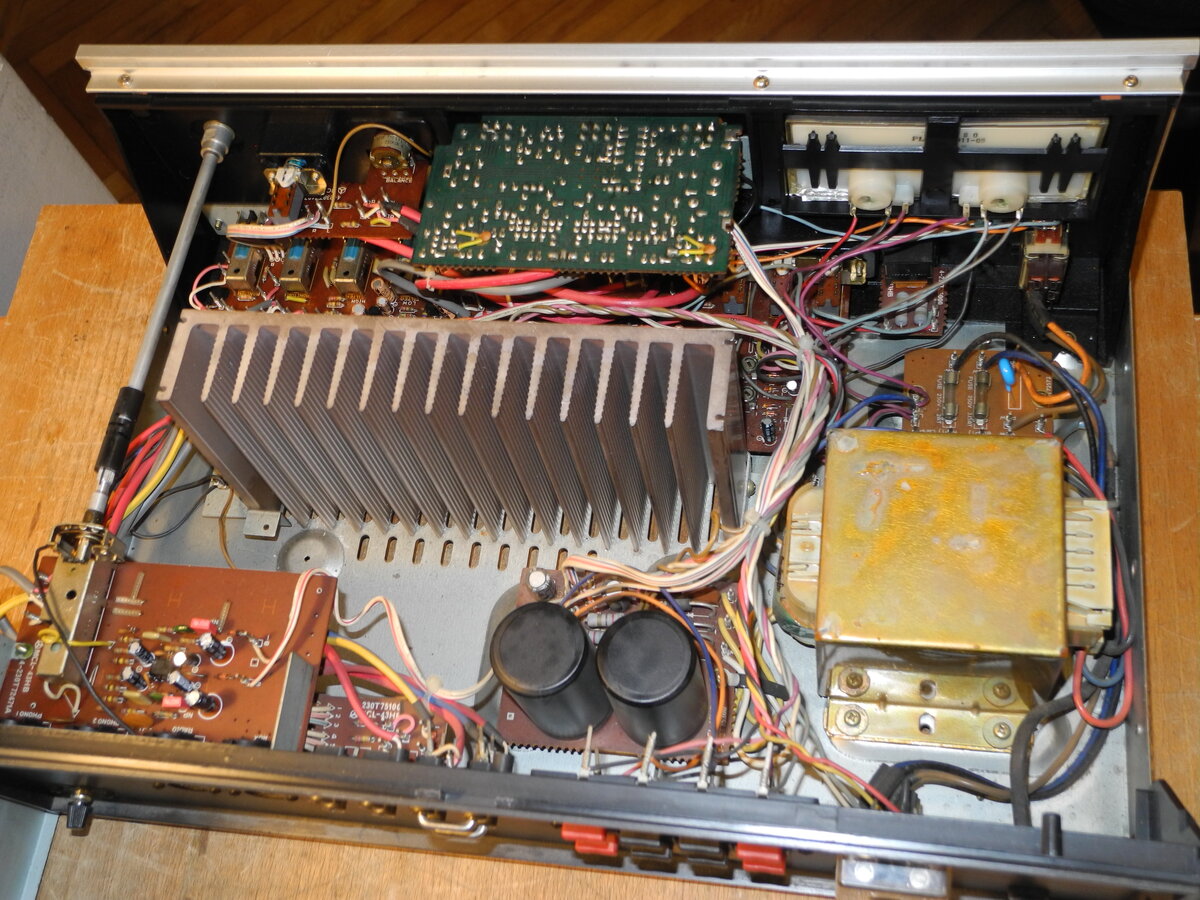
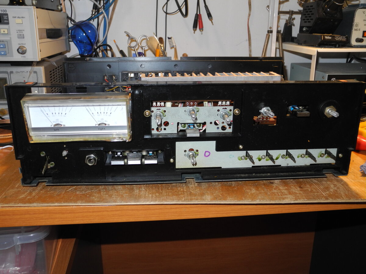
General Specifications
Maximum power (8Ω): 45WTHD (1kHz): <0.1%
Speaker load impedance: 8Ω-16Ω
Dimensions (WHD): 440×150×290mm
Weight: 9kg
Measured Values
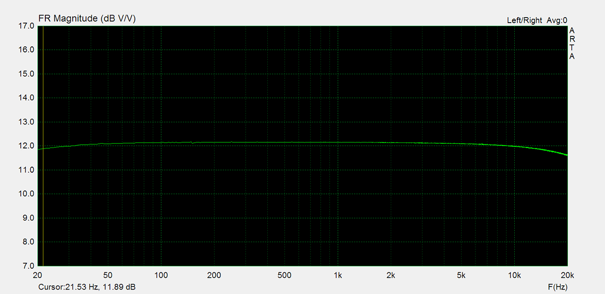
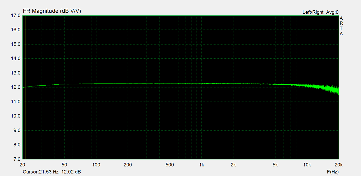
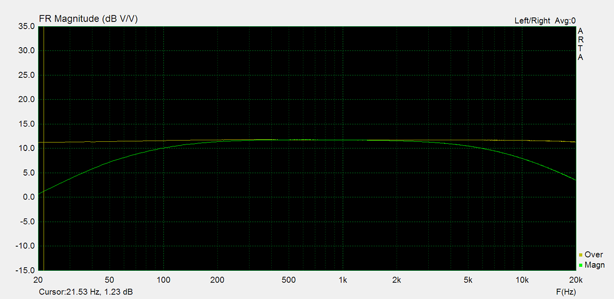
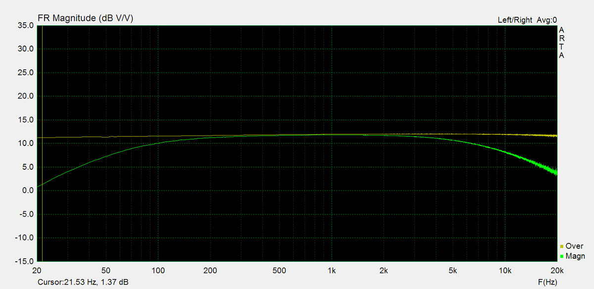
Maximum power (8Ω): 55.8WFrequency response (20Hz-20kHz): <0.6dB
Channel imbalance: <0.2dB
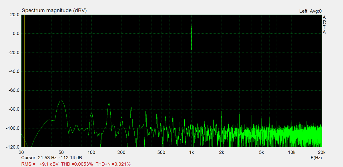
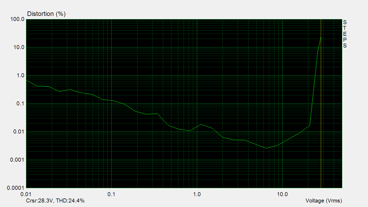
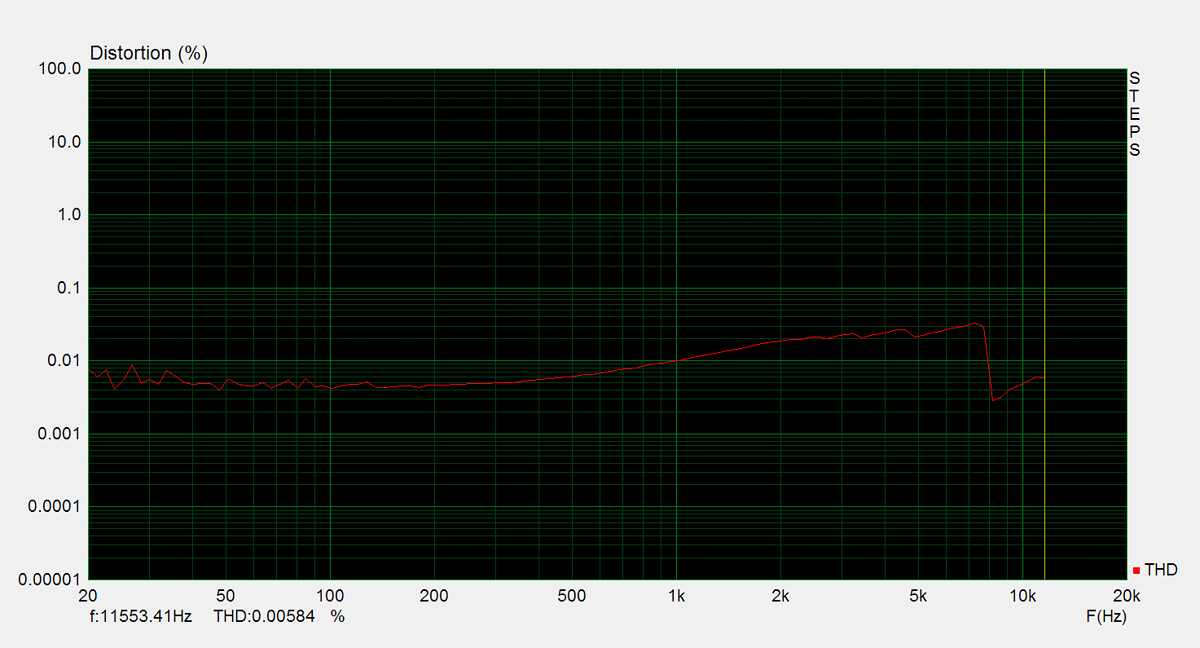
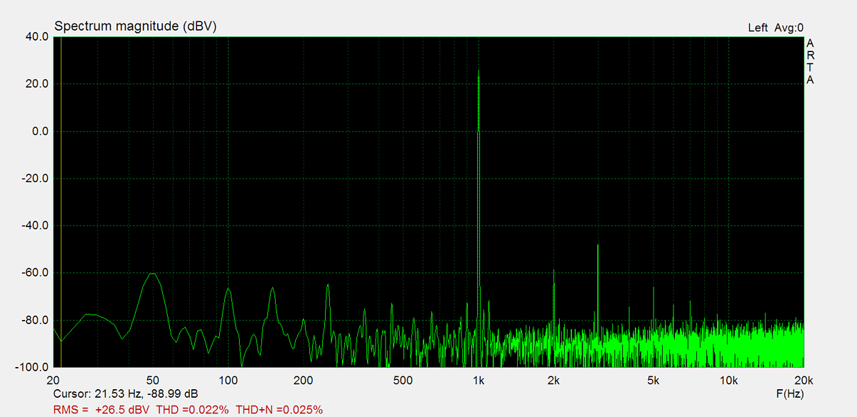
THD (1kHz, 1W): 0.0053%
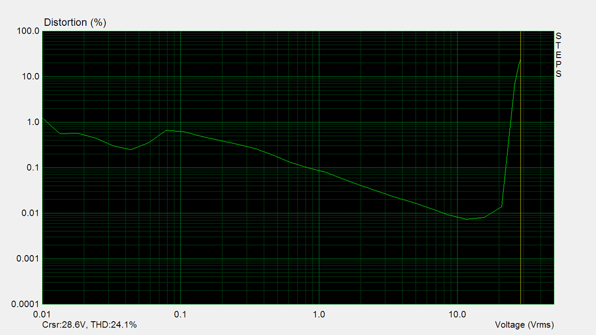
THD+N (1kHz, 1W): 0.021%
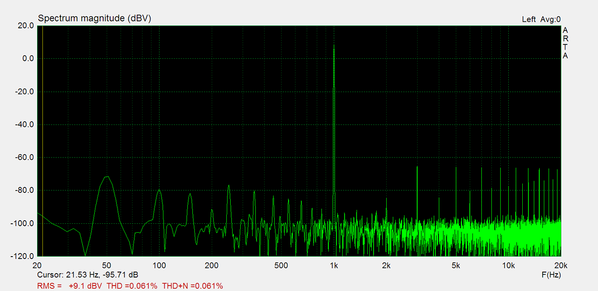
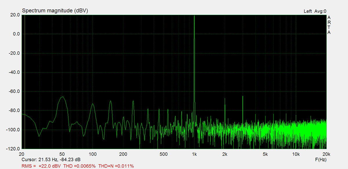
THD (1kHz, 20W): 0.0065%
THD+N (1kHz, 20W): 0.011%
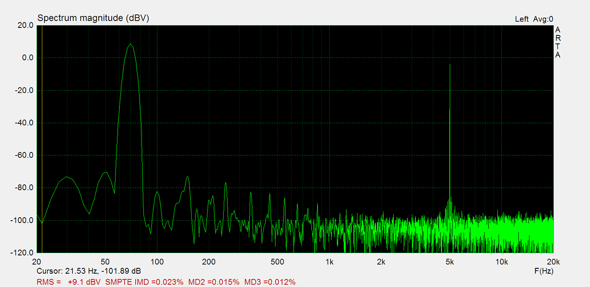
IMD (70Hz, 5kHz, 1W): 0.023%
Chanell separation (1kHz, 1W): 67.5%
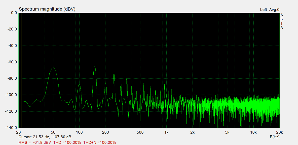
Noise: -61.8dB
Amplification: 130.8
DC offset L: 43.2mV
DC offset R: -93.4mV
Maximum Power
Maximum power is measured using 8Ω resistors on both channels. A 1kHz sine wave input signal is applied and gradually increased until higher harmonics rise significantly. Typically, this is the point at which output clipping occurs.

Frequency Response
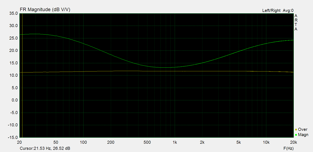
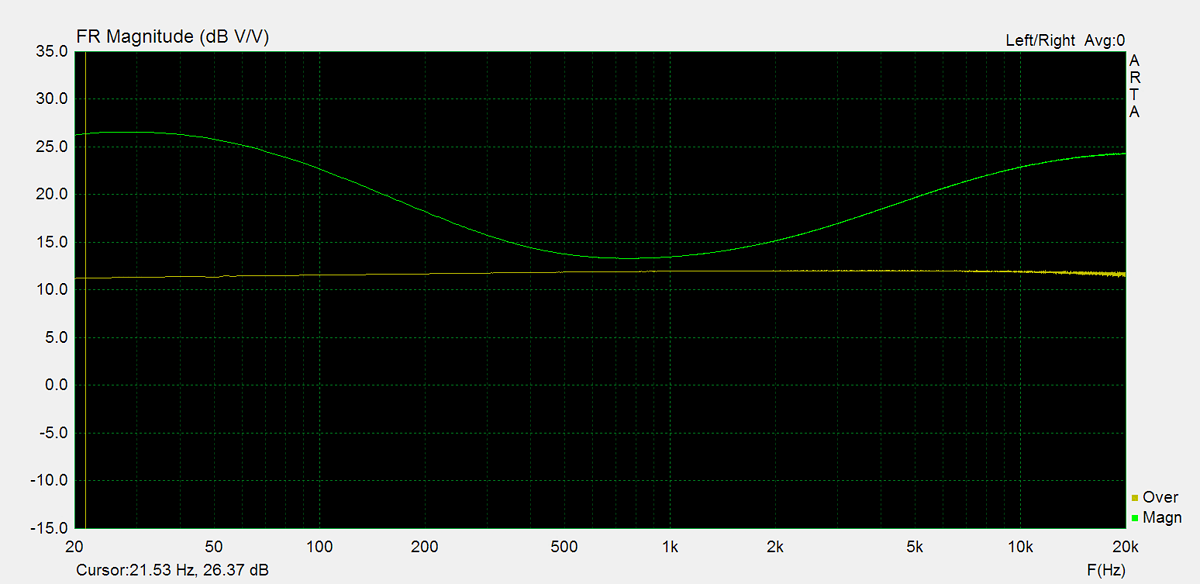
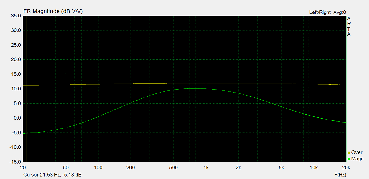
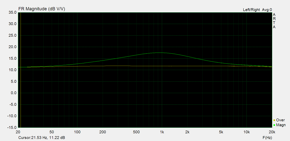
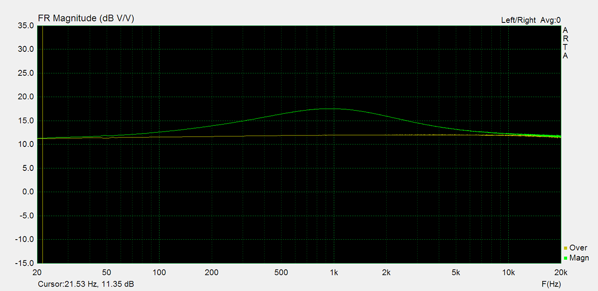
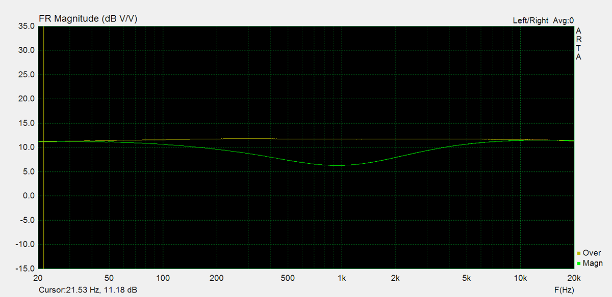
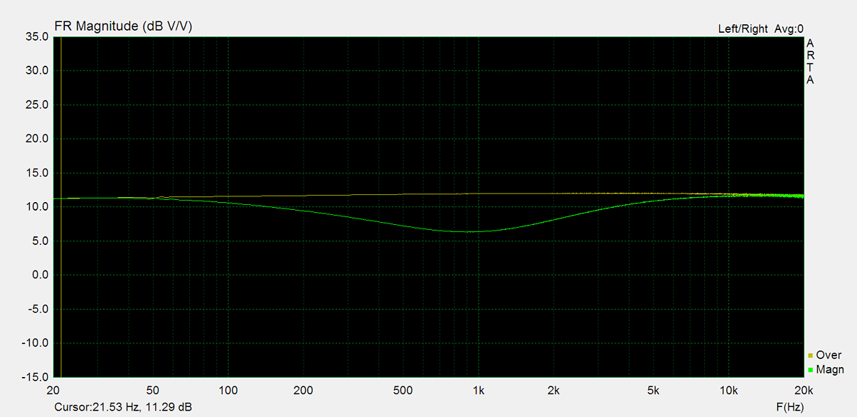
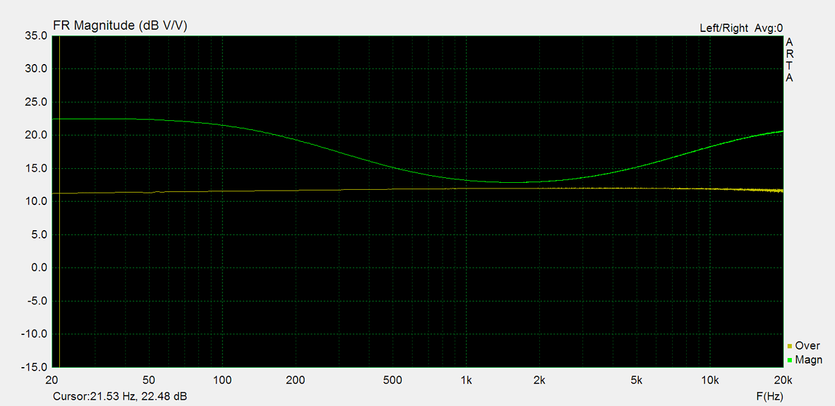
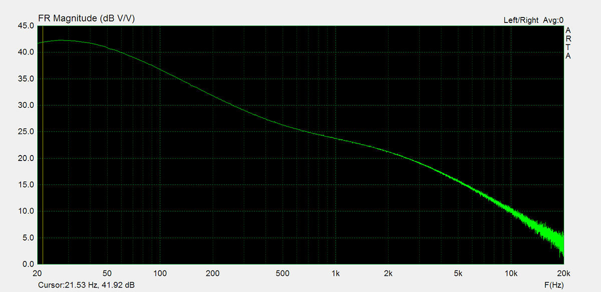
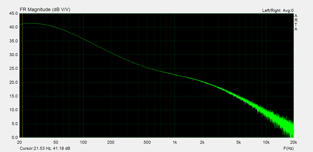
Frequency response is measured using several equalizer settings. 'Flat' indicates the tone controls are either turned off or set to their neutral position. 'Max' and 'Min' refer to the maximum and minimum tone control positions, respectively. In the phono section, the expected response follows the RIAA equalization curve.


Residual Noise
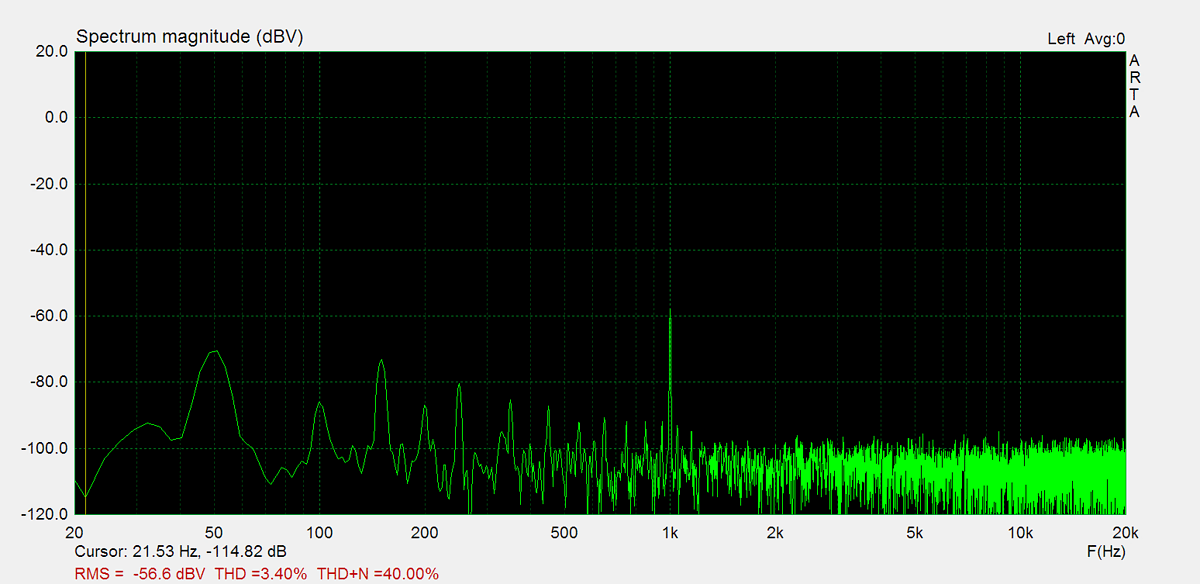
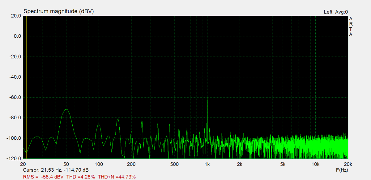
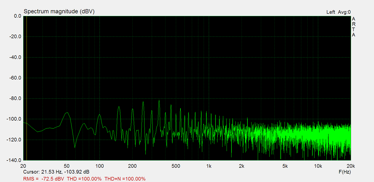
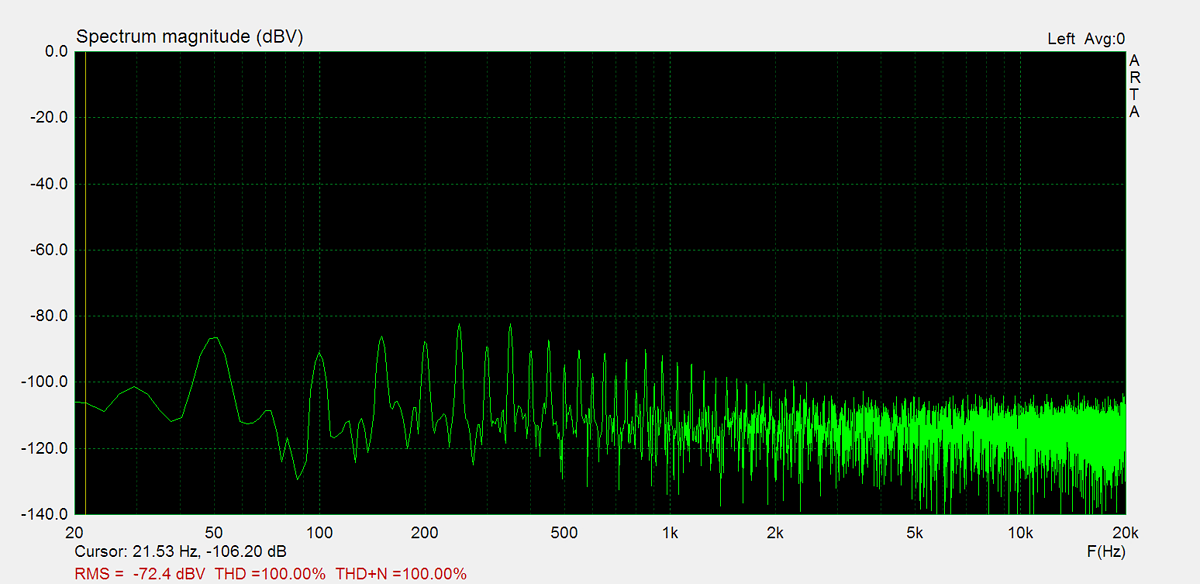
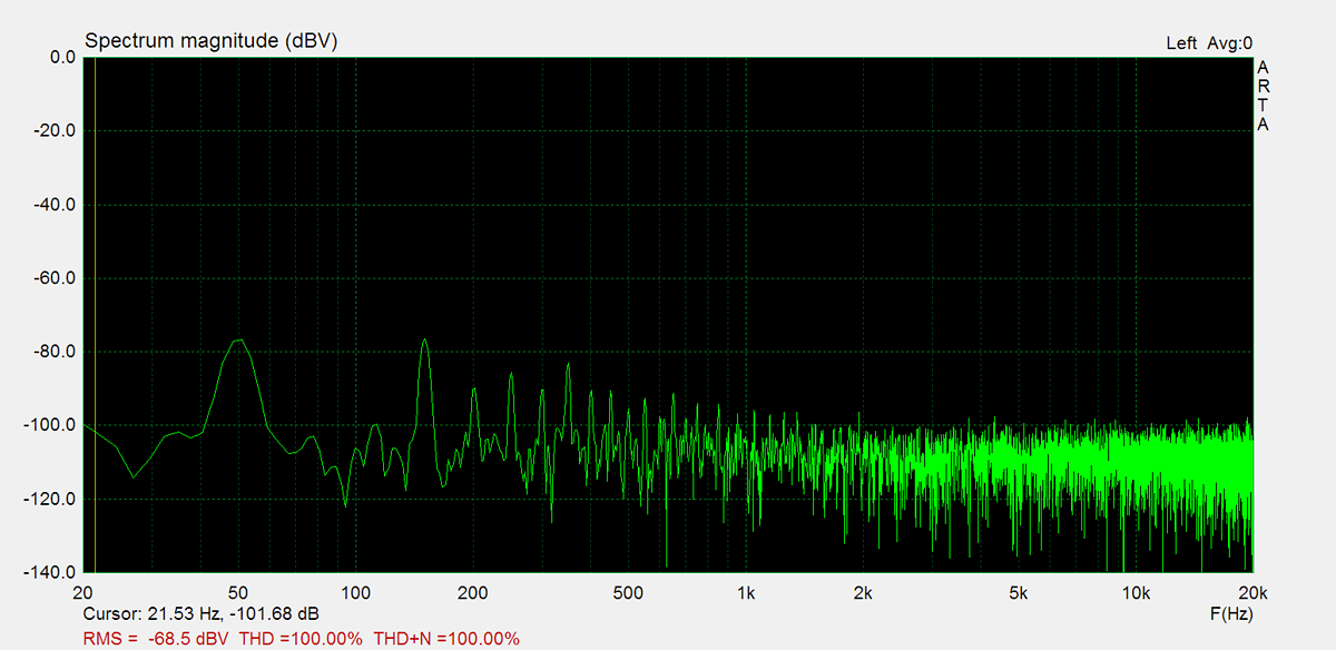
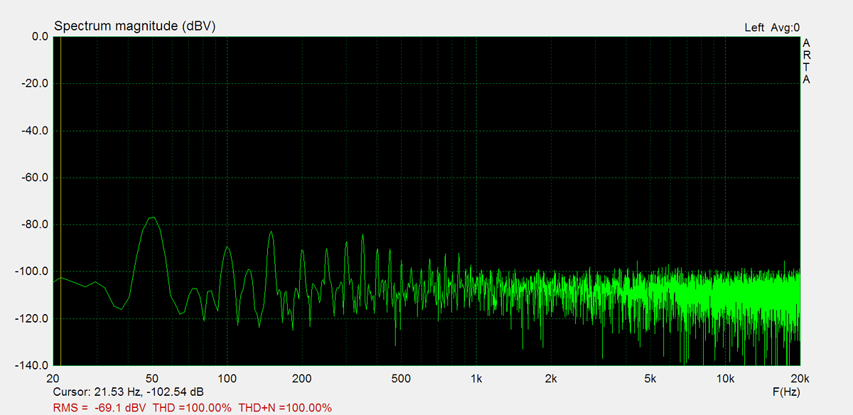
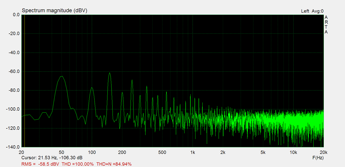
These graphs display the noise levels at various volume positions. To eliminate any interference from the input signal, the input lines are shorted during the measurement. Generally, the noise is highest at the mid-point of the volume range (50%)
Distorsion
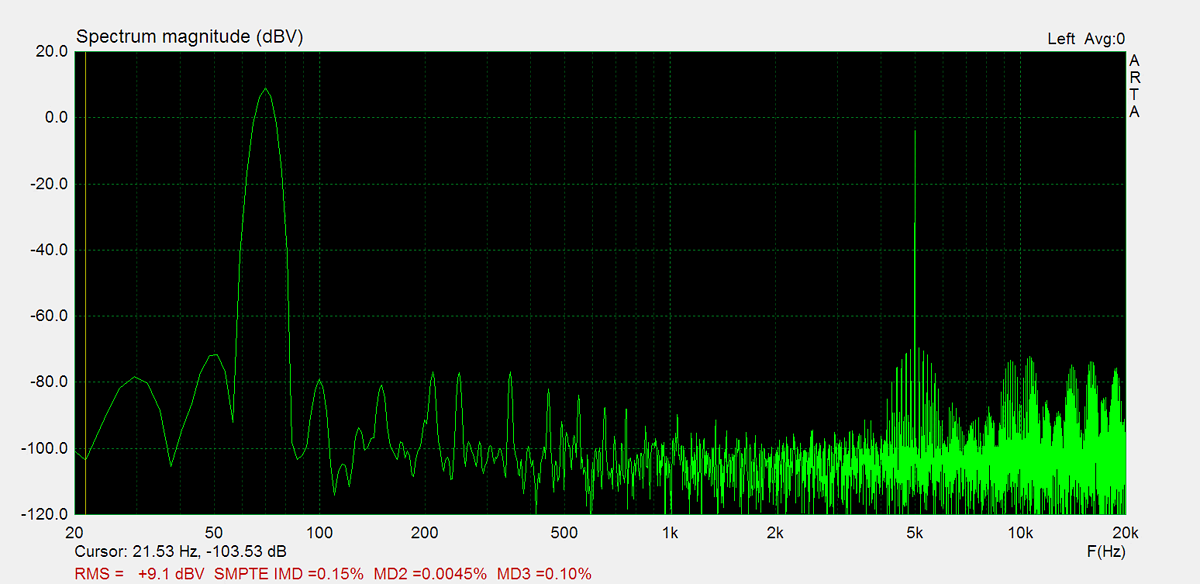
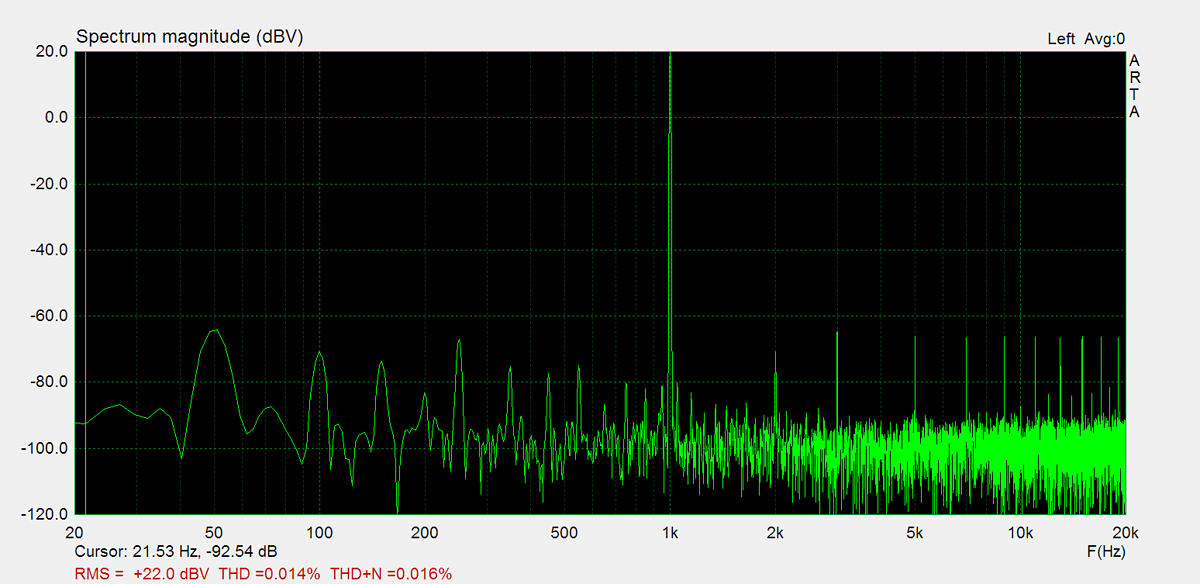
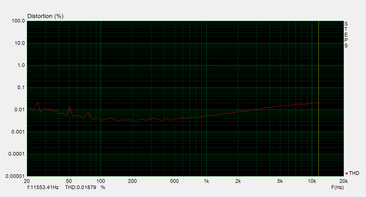
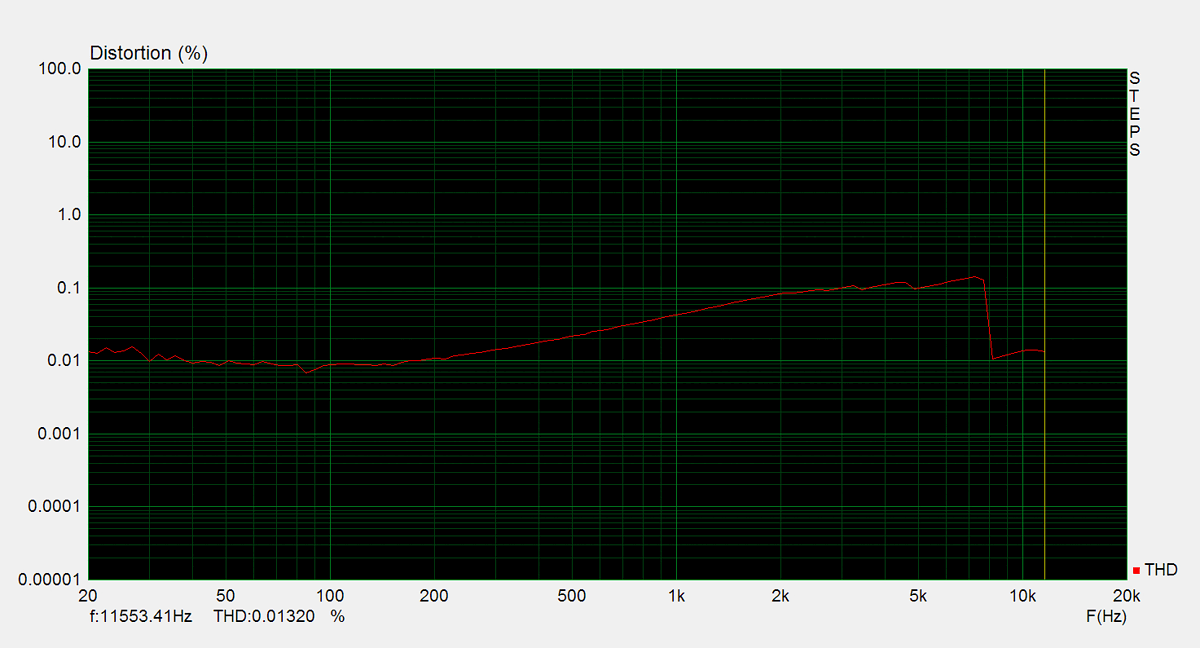
Total harmonic distortion (THD) is measured using a 1kHz sine wave input, with the output level adjusted to meet different conditions. Intermodulation distortion (IMD) is measured using 'two sine' input signal. THD versus voltage is measured with a 1kHz sine wave input, while THD versus frequency is measured at various output levels.