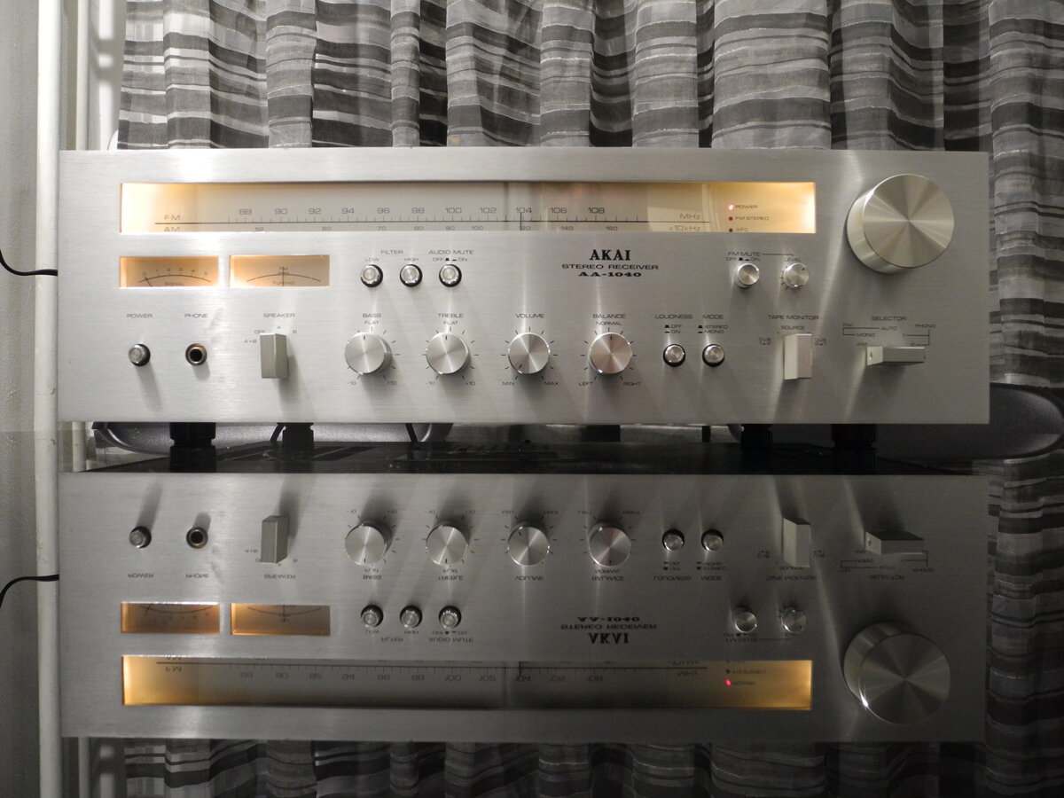
Akai AA-1040
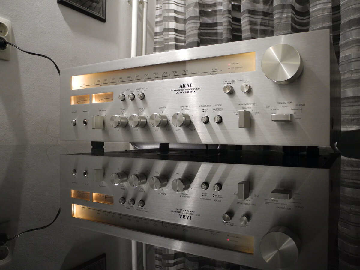
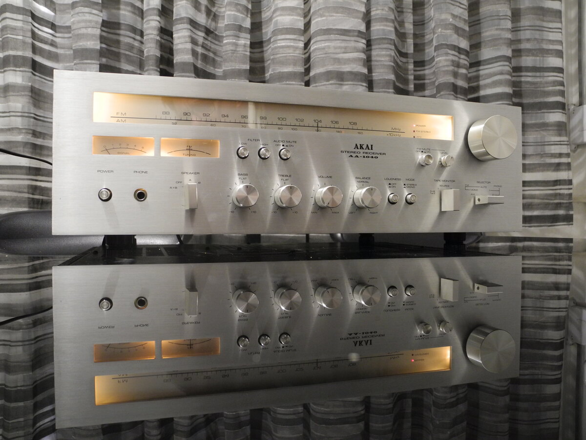
The Akai AA-1040 is a vintage stereo receiver from the late 1970s. It features a classic silver faceplate design and a straightforward, well-organized layout.
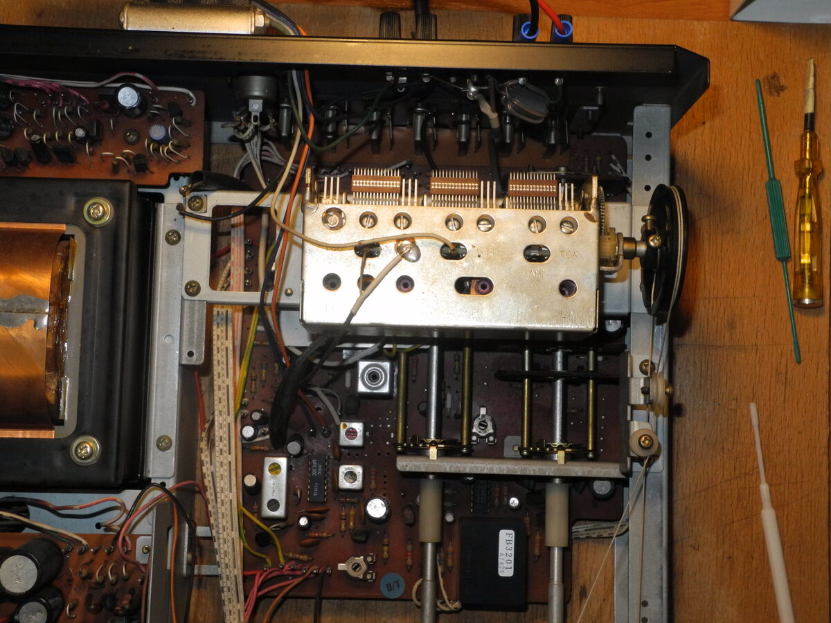
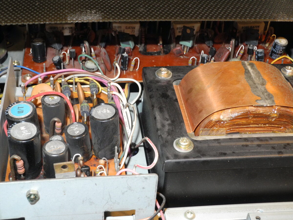
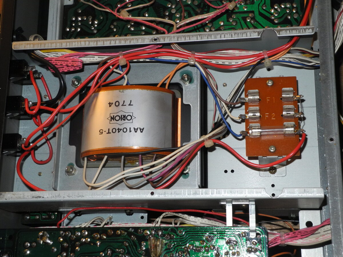
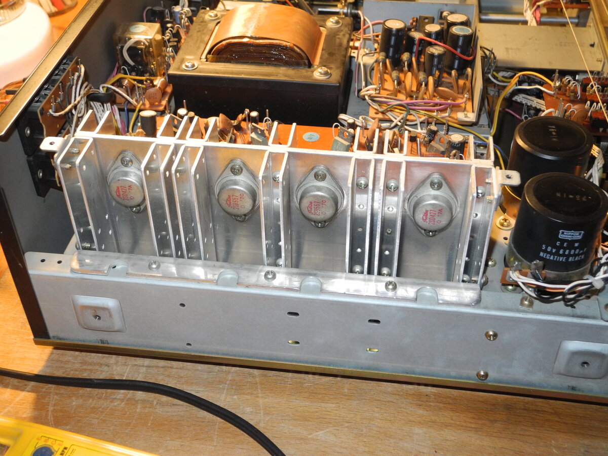
The power supply is filtered by two 6800µF capacitors, offering solid energy reserves. The power amplifier is built around Toshiba 2SB557 and 2SD427 output transistors and includes relay-based speaker protection. Two pairs of speakers are supported.
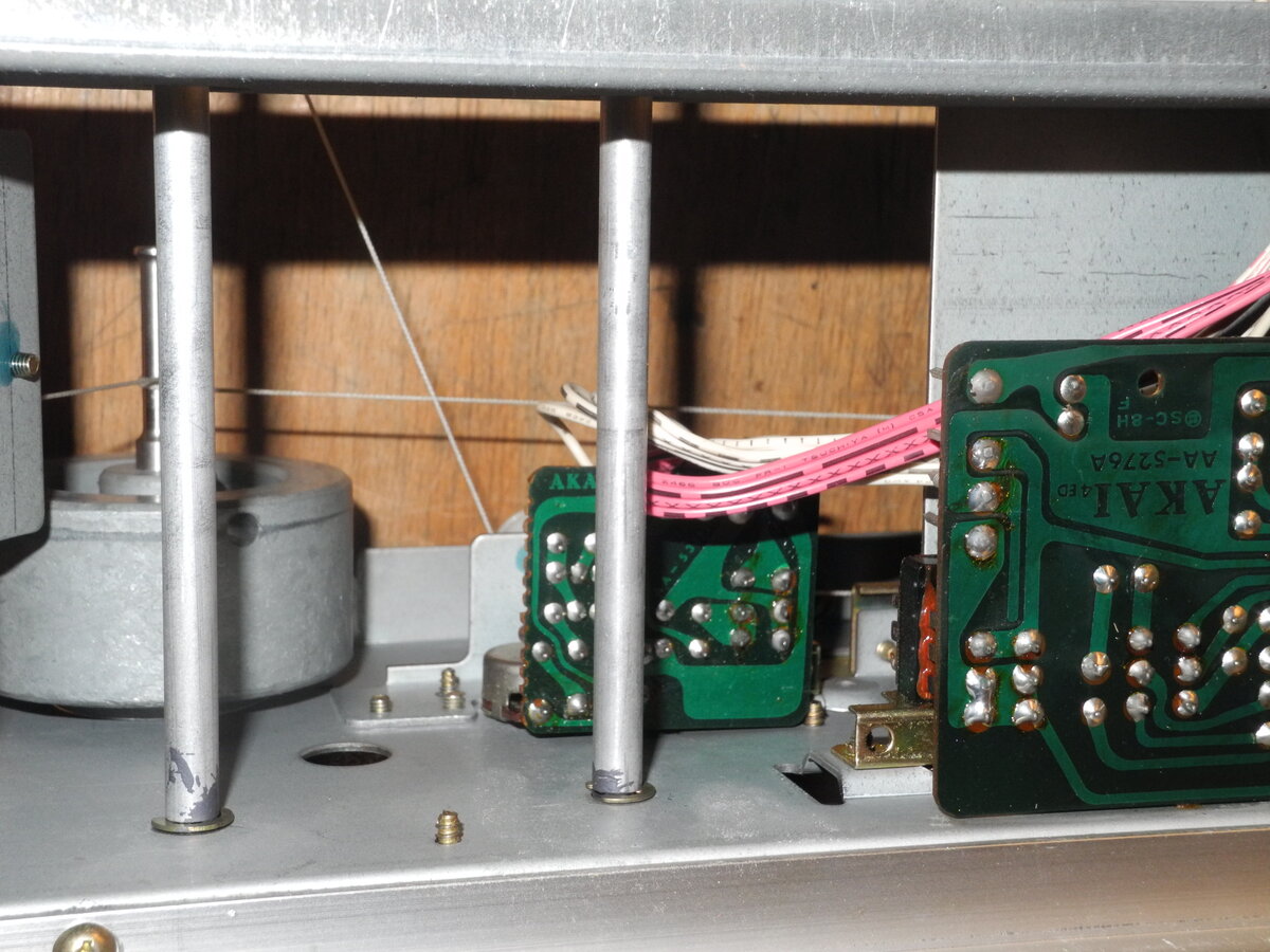
The tuner section uses a 4-gang FM tuning capacitor, offering good reception sensitivity. There are two Phono inputs, but there is no support for MM cartridges.
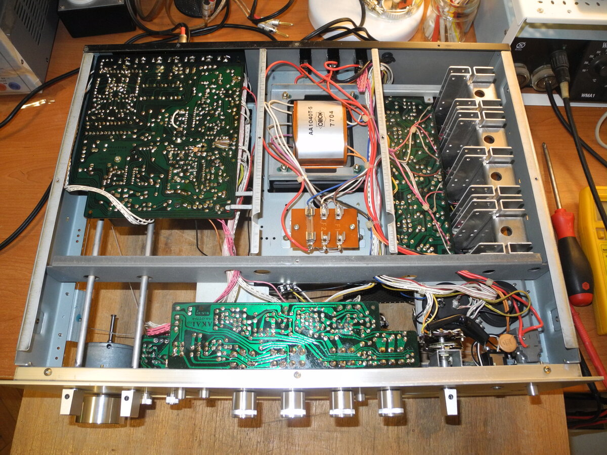
The internal construction is solid, and the components are accessible. This makes servicing and maintenance a lot easier.
Audio signature is warm, smooth, and clean. The AA-1040 is a testament to Akai's reputation for excellence in audio equipment during the golden era of hi-fi.
Manufacturer: Akai
Status: Defunct company
Source: Wikipedia (Akai)


General Specifications
Maximum power (8Ω): 40WFrequency response (-3dB): 7Hz-70kHz
THD+N: 0.15%
Signal to noise ratio (Line): 90dB
Signal to noise ratio (Phono): 80dB
Input sensitivity (Line): 150mV
Input sensitivity (Phono): 3mV
Chanel separation (Phono): 60dB
Speaker load impedance: 8Ω-16Ω
Dimensions (WHD): 480×155×390mm
Weight: 12.8kg
Produced: 1976-1977
Initial price: 1000DM
Measured Values
Maximum power (8Ω): 48WFrequency response (20Hz-20kHz): <0.6dB
Channel imbalance: <2.0dB
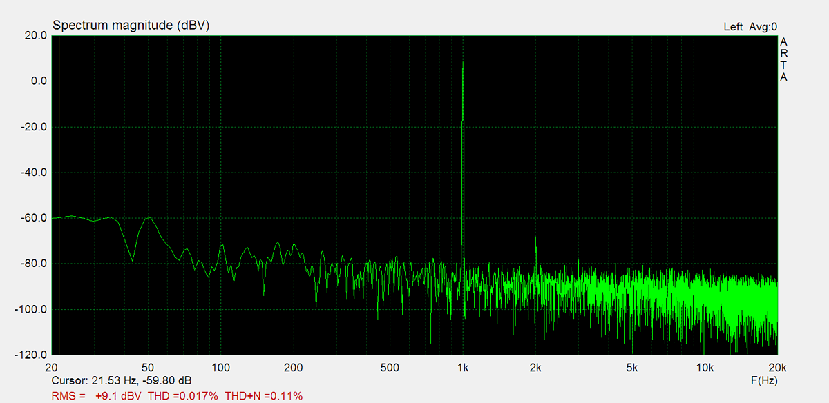
THD (1kHz, 1W): 0.017%
THD+N (1kHz, 1W): 0.11%
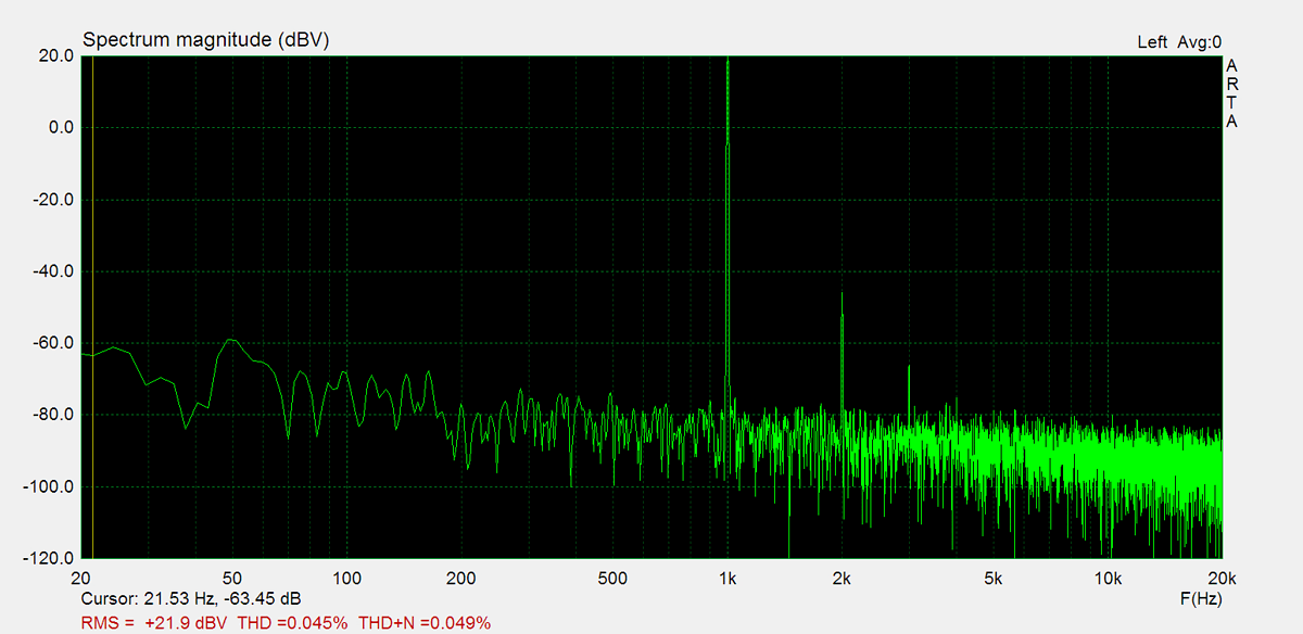
THD (1kHz, 20W): 0.045%
THD+N (1kHz, 20W): 0.049%
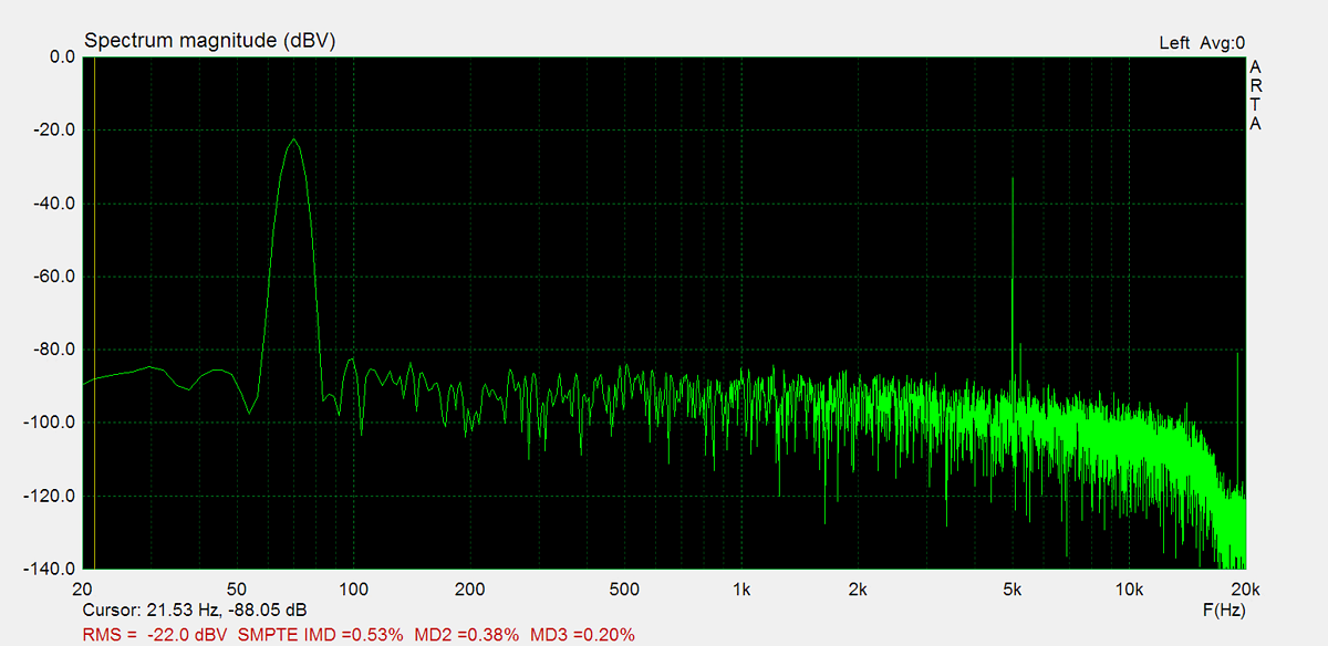
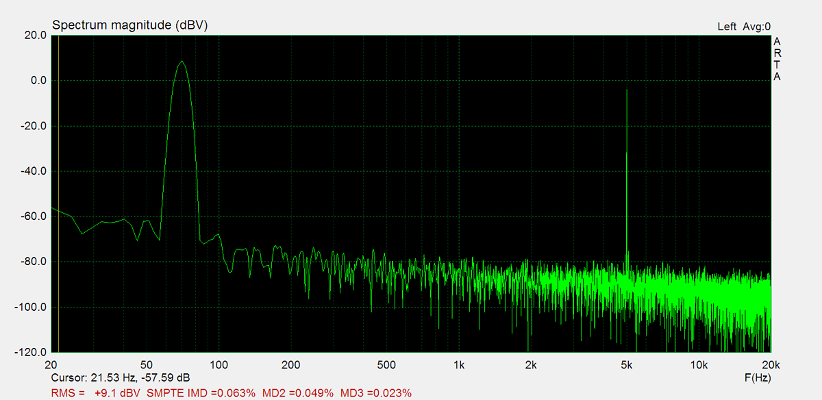
IMD (70Hz, 5kHz, 1W): 0.063%
Noise: -41.7dB
Amplification: 132.6
DC offset L: 16.3mV
DC offset R: 15.2mV
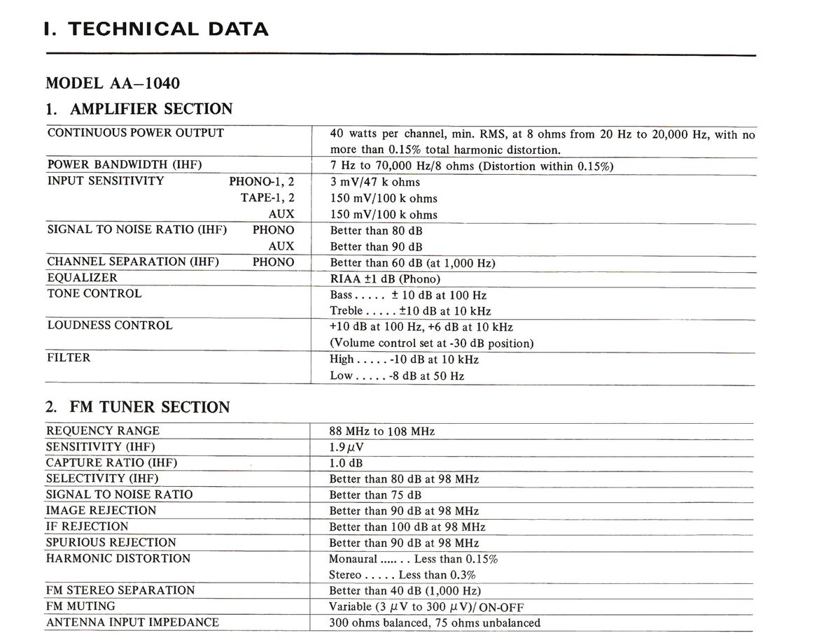
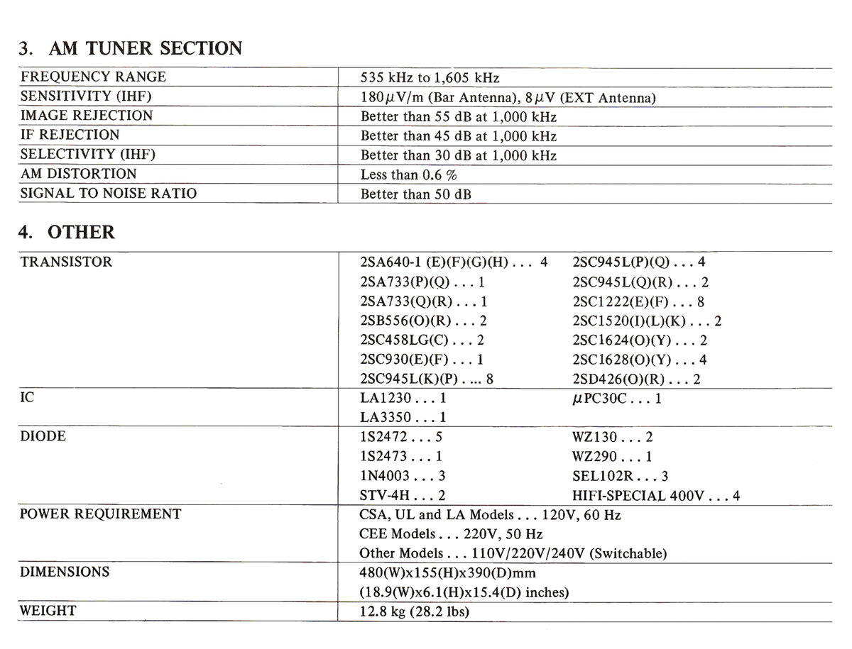
Factory Specification Sheet
Factory specification images are sourced directly from the device's original service manual or user manual. These documents are produced by the manufacturer and provide authoritative information on the product's specifications.
Maximum Power
Maximum power is measured using 8Ω resistors on both channels. A 1kHz sine wave input signal is applied and gradually increased until higher harmonics rise significantly. Typically, this is the point at which output clipping occurs.
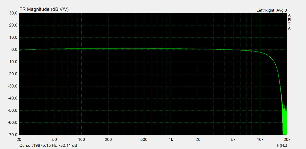
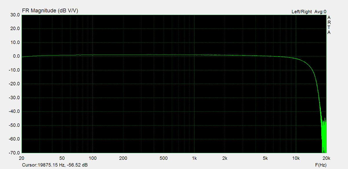
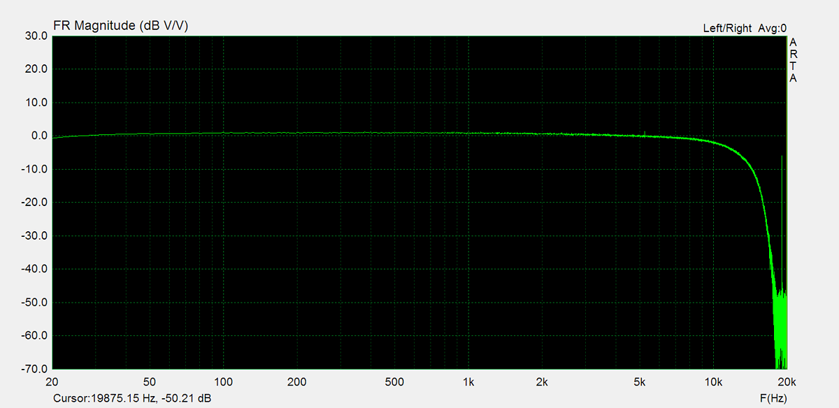
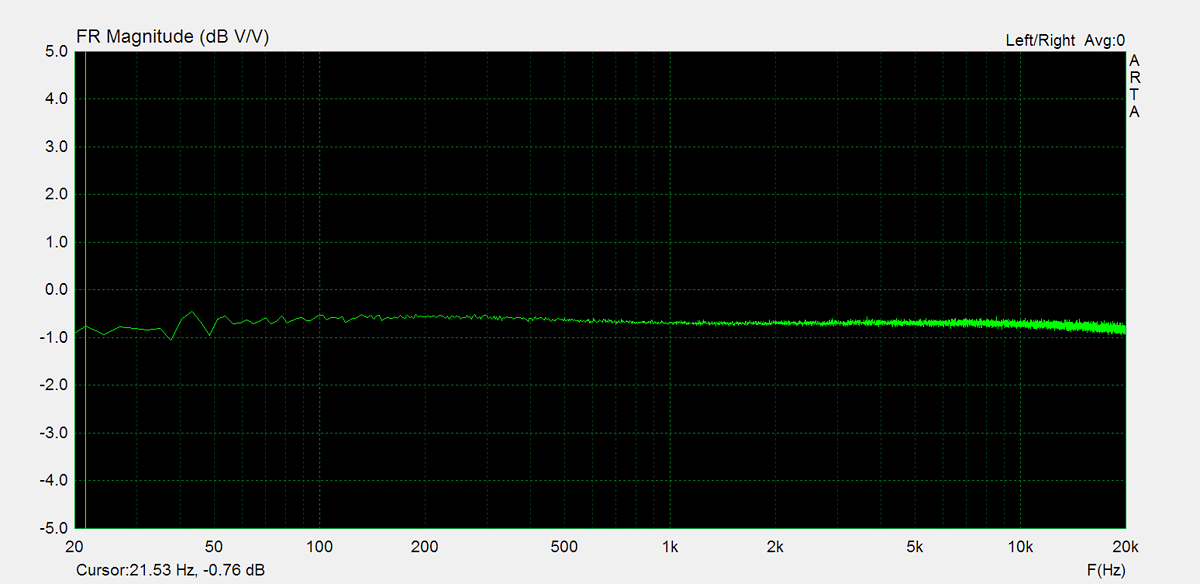
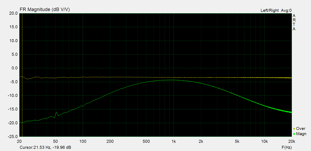
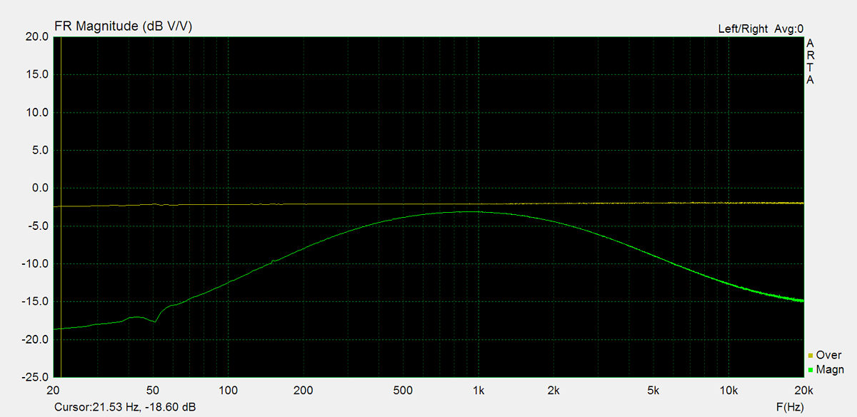
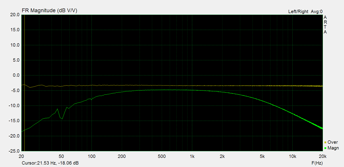
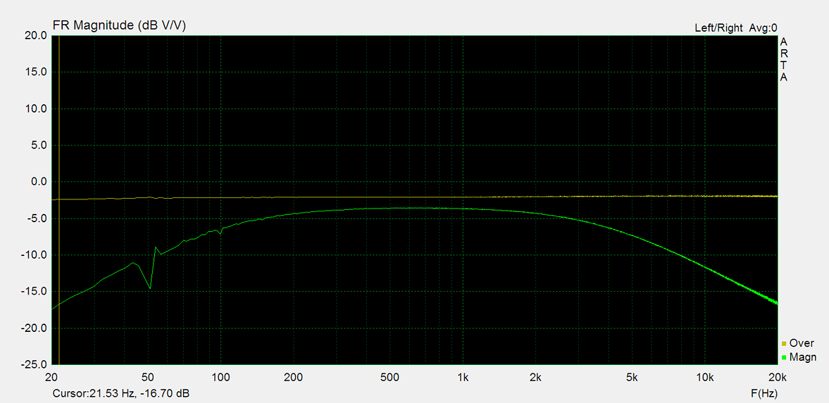
Frequency Response
Frequency response is measured using several equilizer settings. 'Flat' indicates the tone controls are either turned off or set to their neutral position. 'Max' and 'Min' refer to the maximum and minimum tone control positions, respectively. In the phono section, the expected response follows the RIAA equalization curve.


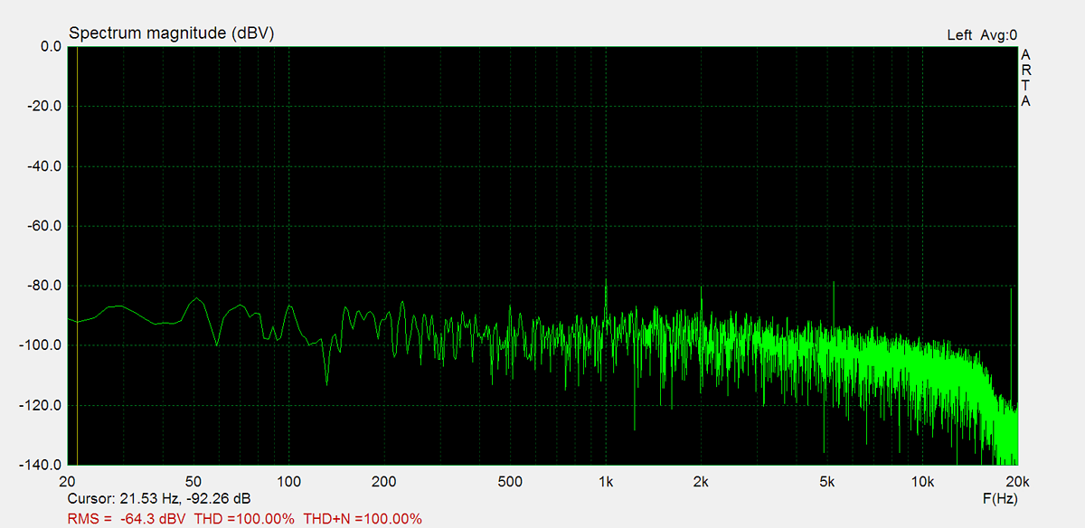
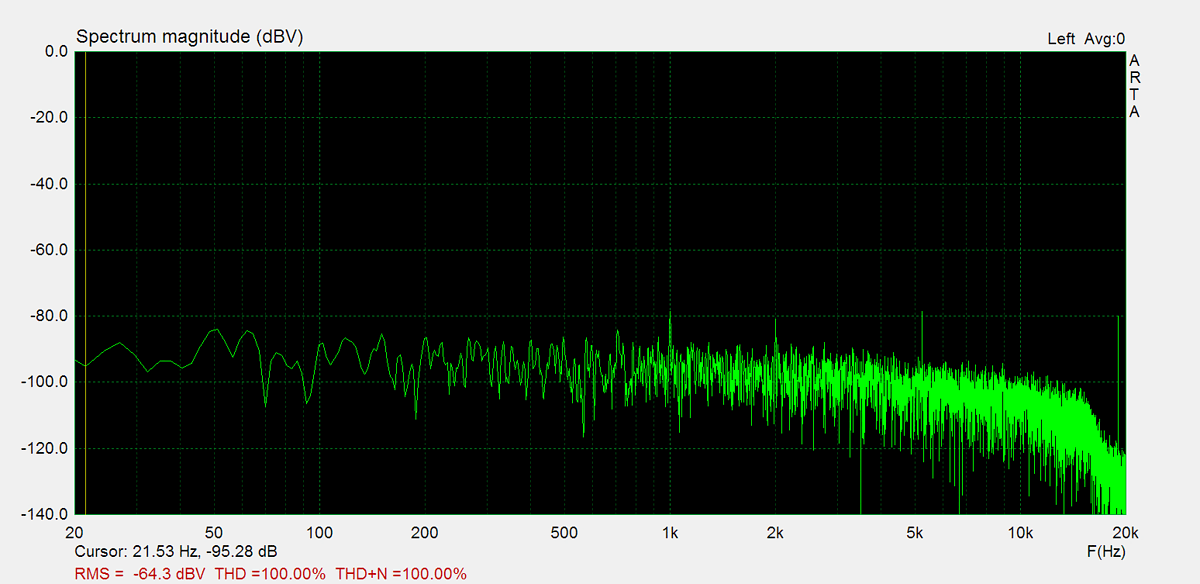
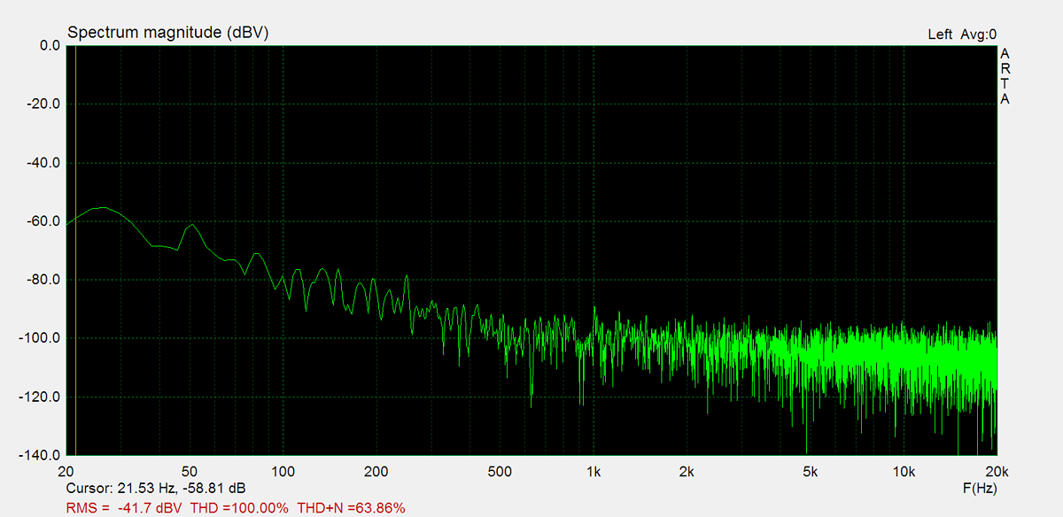
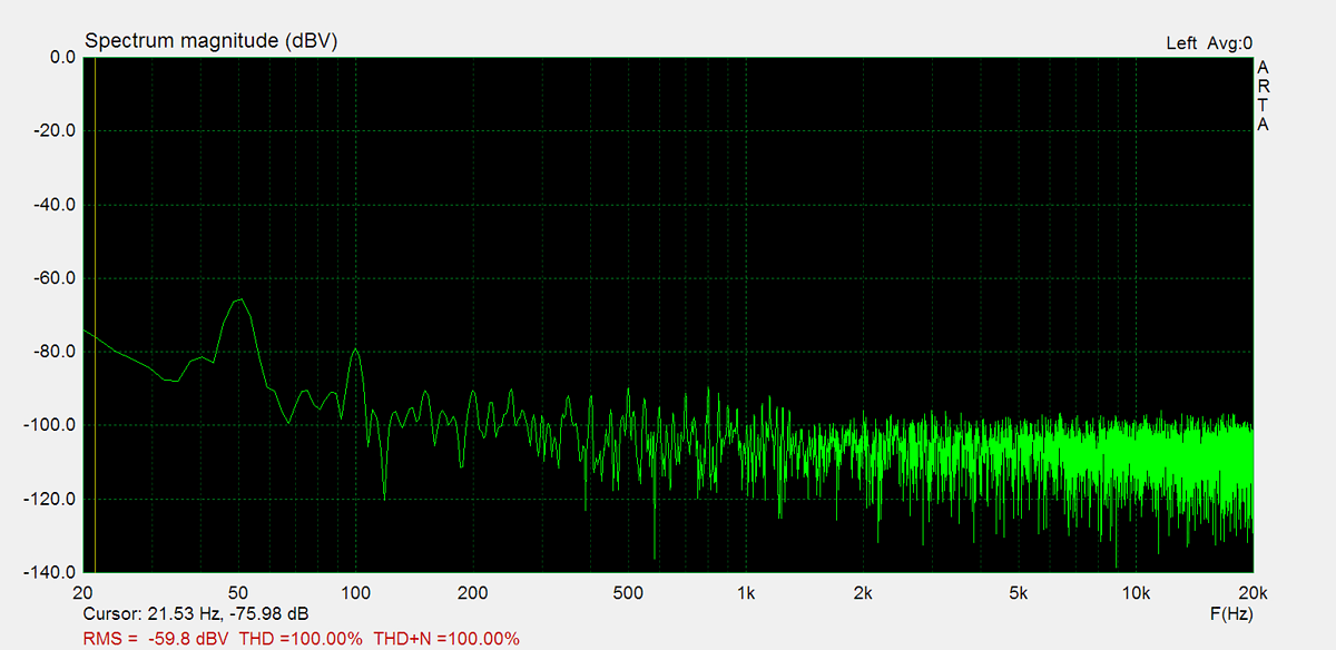
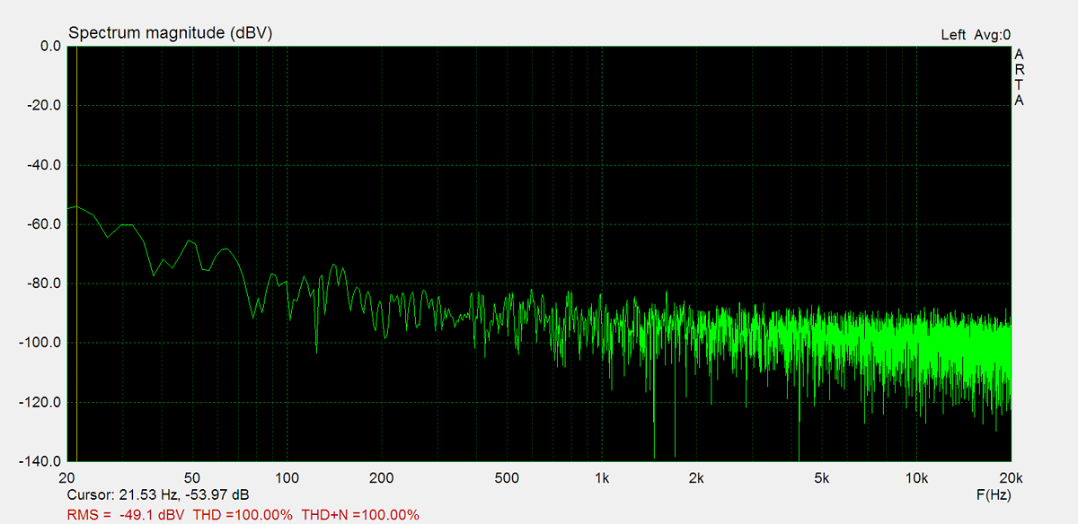
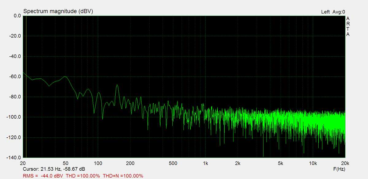
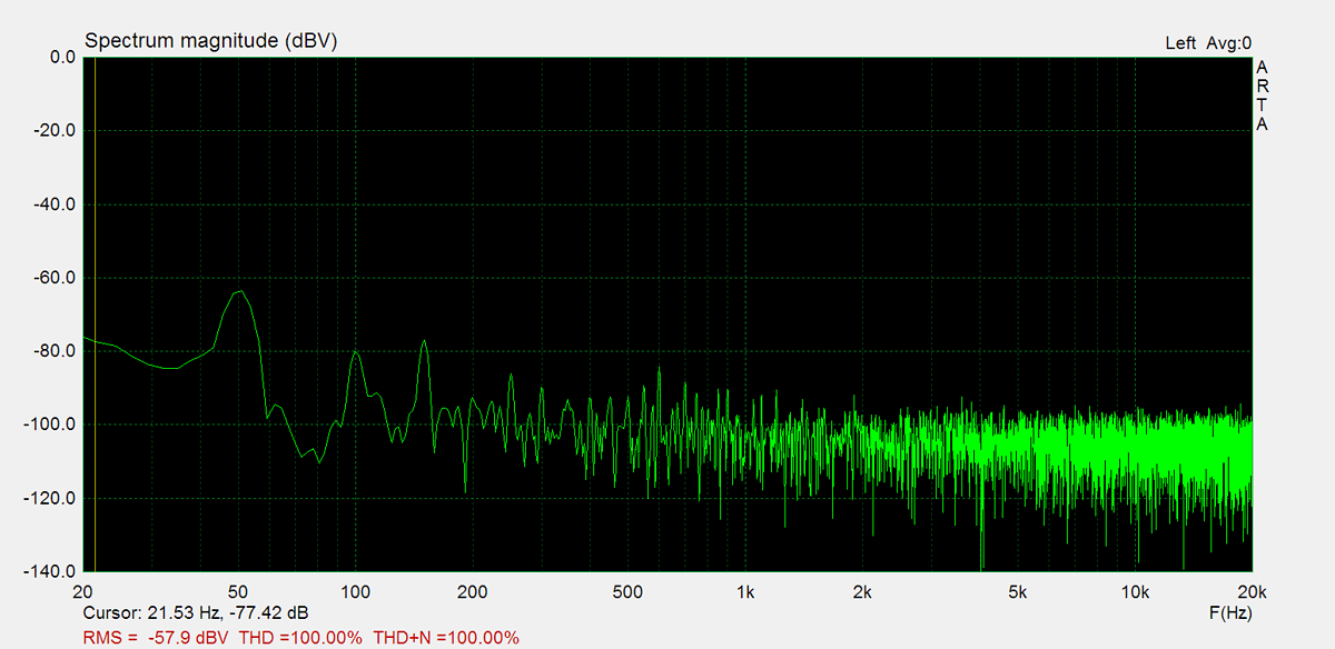
Residual Noise
These graphs display the noise levels at various volume positions. To eliminate any interference from the input signal, the input lines are shorted during the measurement. Generally, the noise is highest at the mid-point of the volume range (50%)

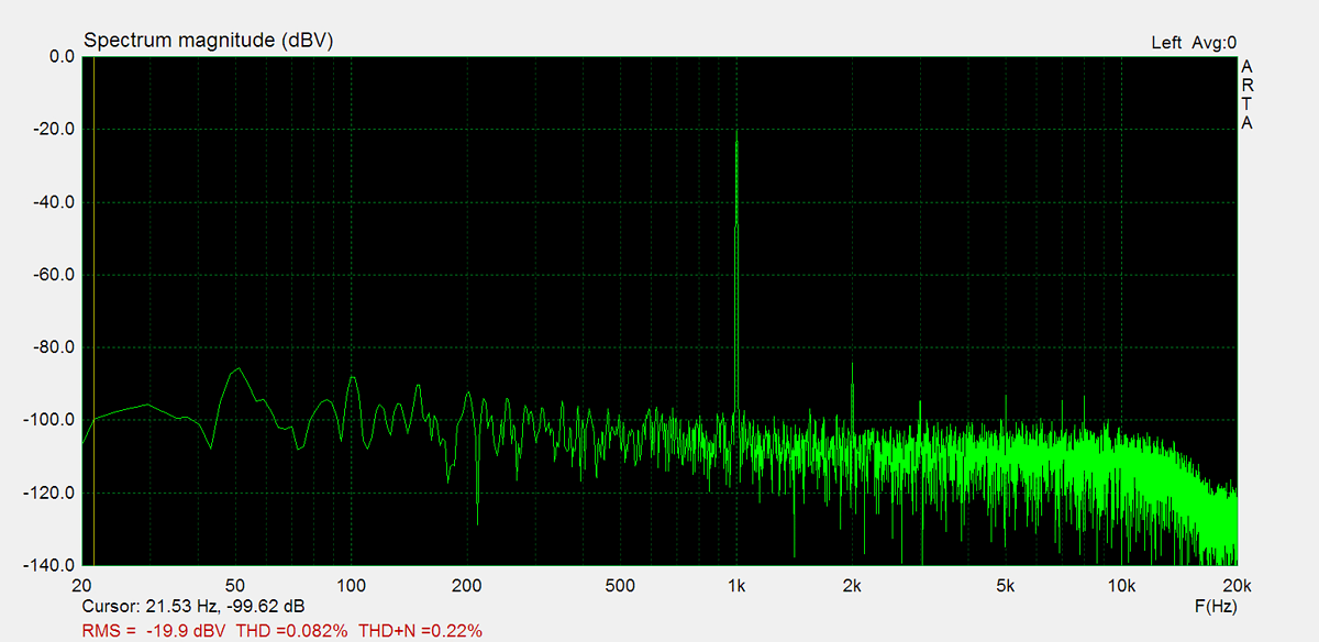
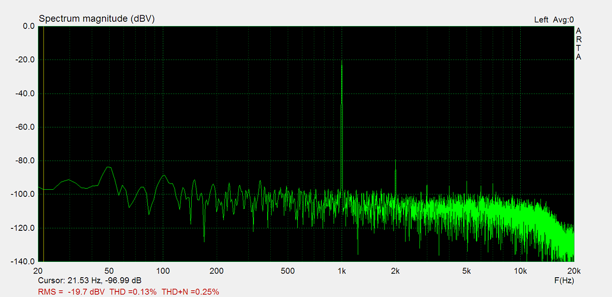
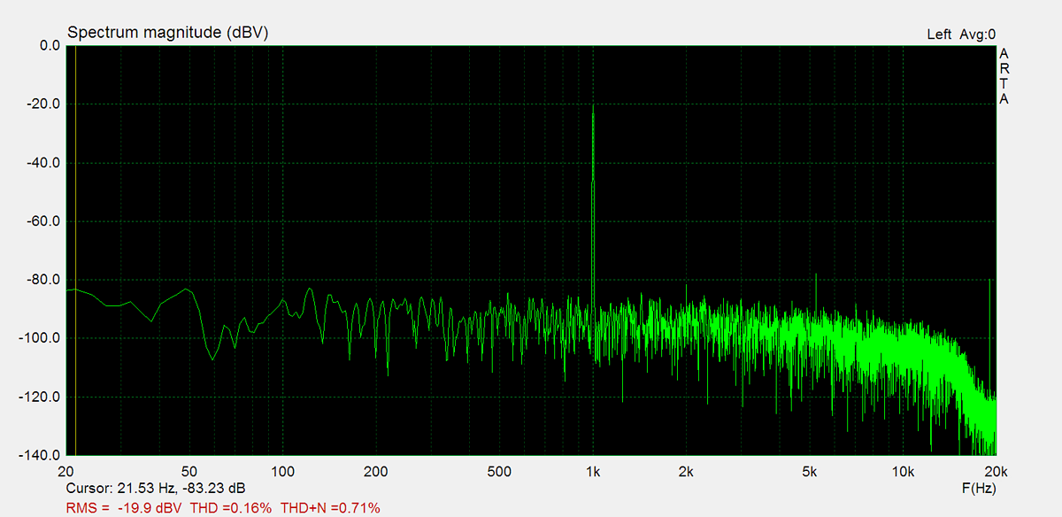
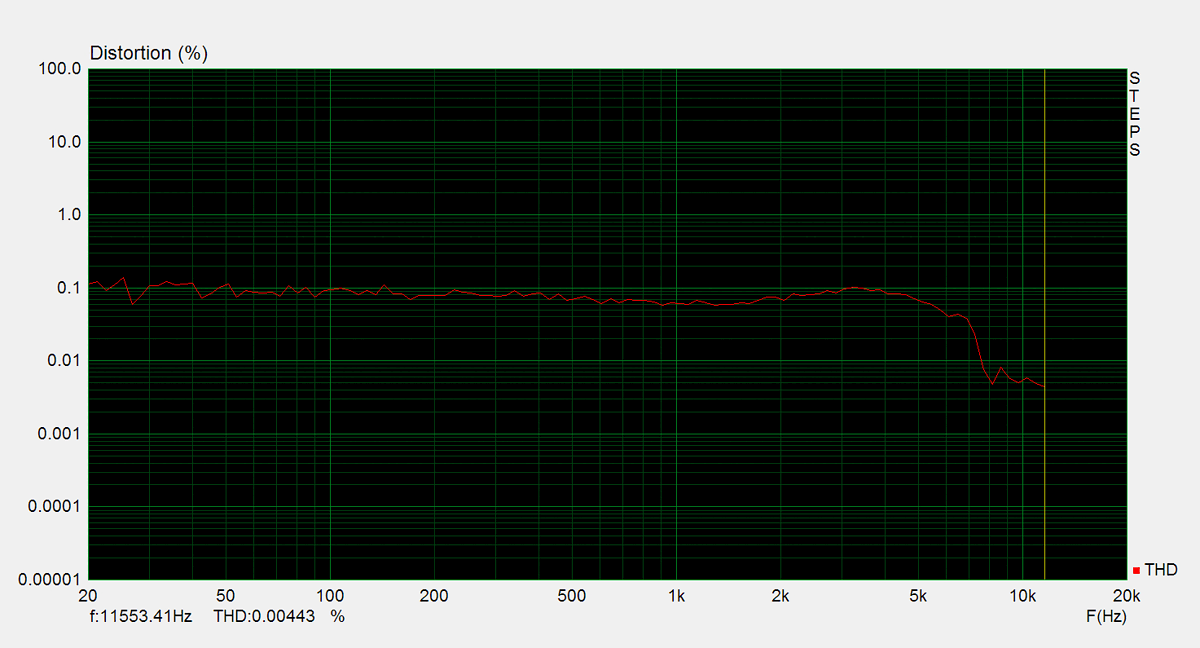
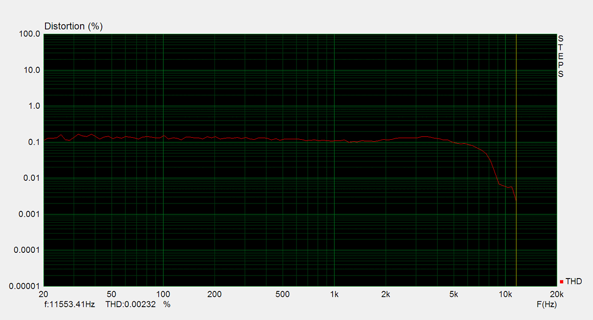
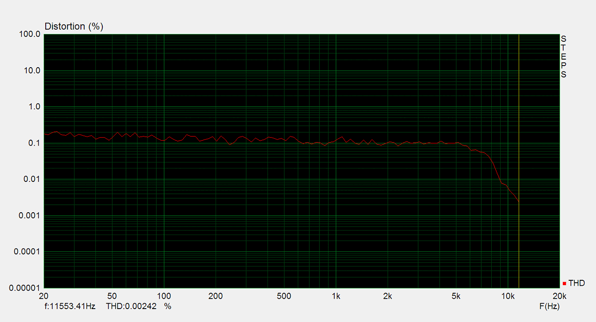
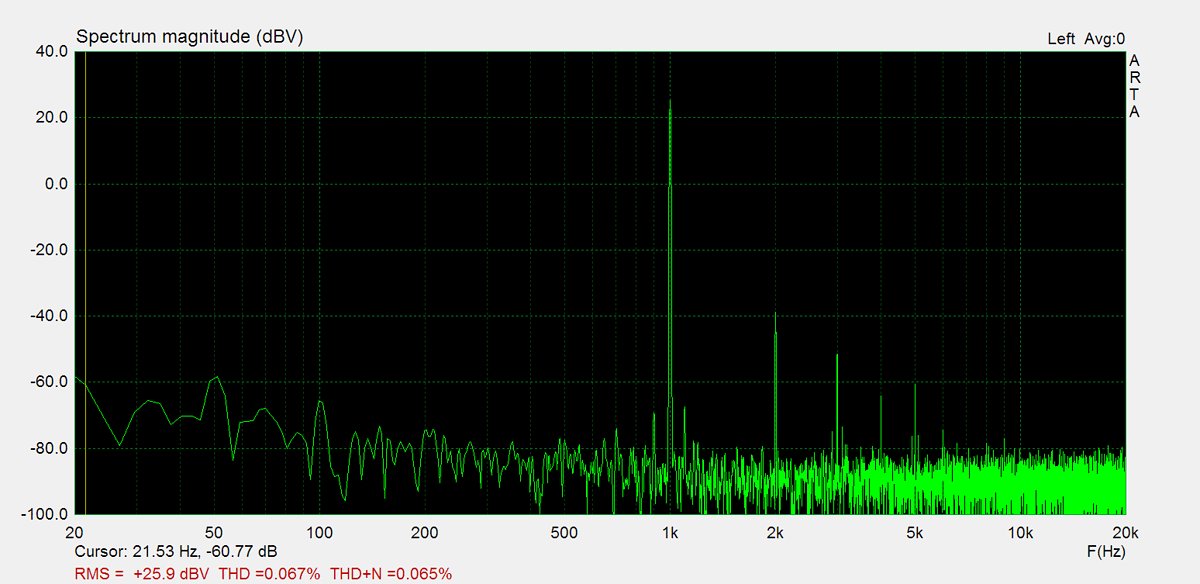
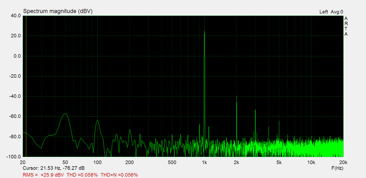
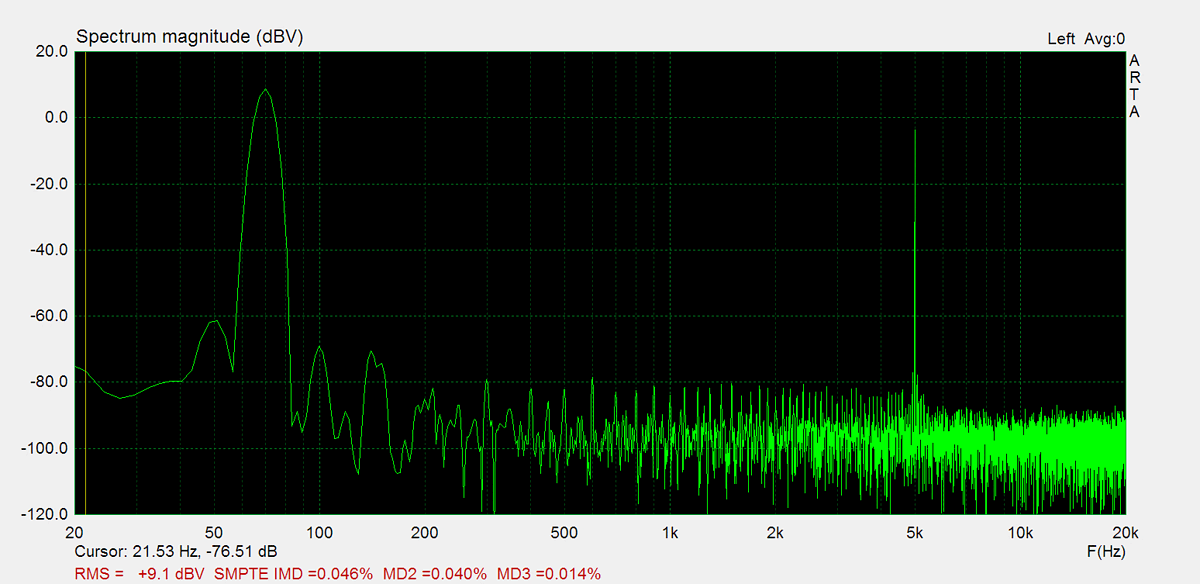
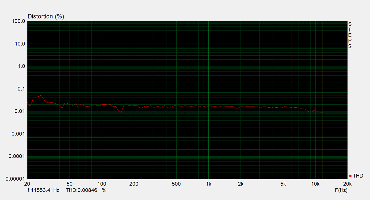
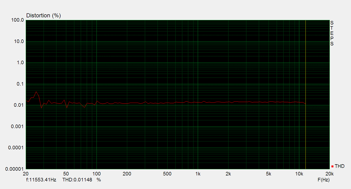
Distorsion
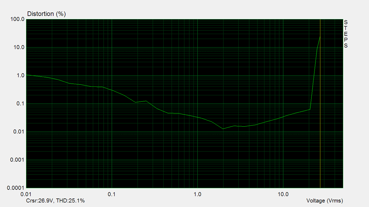
Total harmonic distortion (THD) is measured using a 1kHz sine wave input, with the output level adjusted to meet different conditions. Intermodulation distortion (IMD) is measured using 'two sine' input signal. THD versus voltage is measured with a 1kHz sine wave input, while THD versus frequency is measured at various output levels.


FM Tuner
Measurements of the tuner section were performed using an FM signal generator, with its output fed directly into the antenna input. AM measurements were not conducted.