
Akai AA-6200
The Akai AA-6200 is a vintage solid-state stereo receiver from the late 1960s, featuring classic styling with a wooden cabinet and a construction approach typical of hi-fi equipment from that era.
The power amplifier section is based on two STK015 hybrid modules and uses a single-rail power supply design. There are two 1000µF output coupling capacitors, a common solution at the time that can result in reduced bass response at higher output levels. On the positive side, this design eliminates DC offset at the speaker outputs.
The FM tuner section features a 3-gang tuning capacitor, providing solid tuning performance and good station selectivity.
The overall design emphasizes reliability and warm vintage sound, making the AA-6200 a representative example of Akai's early stereo receiver lineup.
Manufacturer: Akai
Status: Defunct company
Source: Wikipedia (Akai)


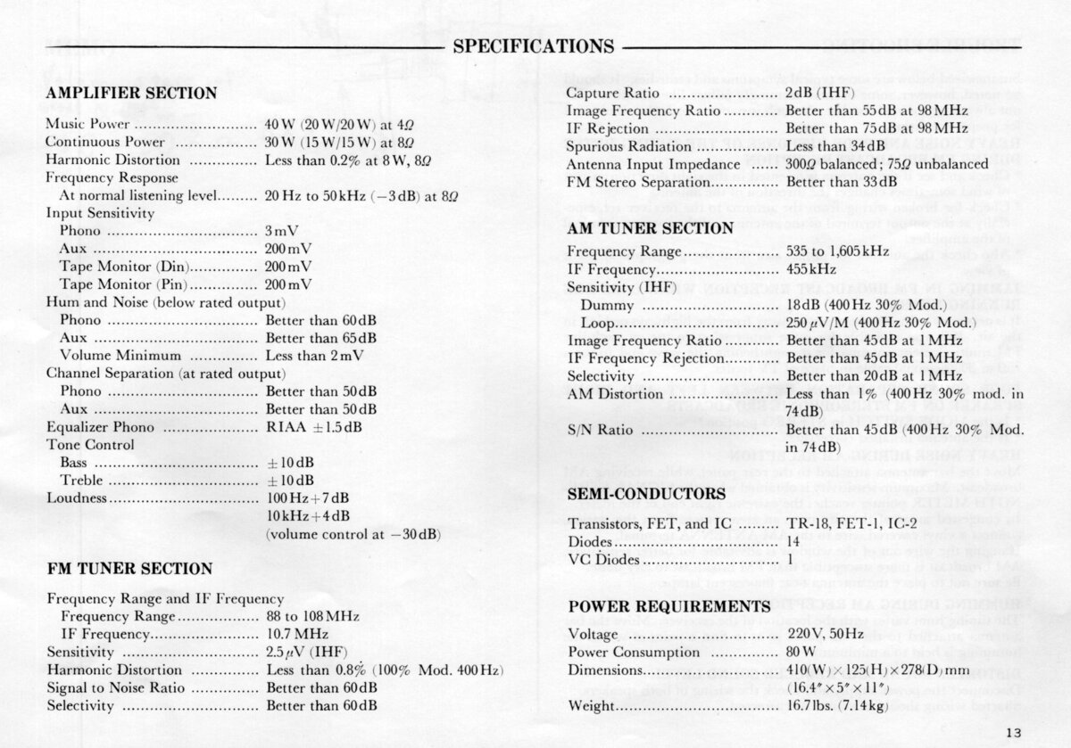
General Specifications
Maximum power (8Ω): 15WMaximum power (4Ω): 20W
Frequency response (-3dB): 20Hz-50kHz
THD+N: 0.2%
Signal to noise ratio (Line): 65dB
Signal to noise ratio (Phono): 60dB
Input sensitivity (Line): 200mV
Input sensitivity (Phono): 3mV
Chanell separation: 50dB
Speaker load impedance: 4Ω-16Ω
Dimensions (WHD): 410×125×278mm
Weight: 7.6kg
Produced: 1968
Initial price: 100USD
Measured Values
Maximum power (8Ω): 10WFrequency response (20Hz-20kHz): <4.0dB
Channel imbalance: <1.0dB
THD (1kHz, 1W): 0.14%
THD+N (1kHz, 1W): 0.18%
THD (1kHz, 5W): 0.28%
THD+N (1kHz, 5W): 0.28%
IMD (70Hz, 5kHz, 1W): 0.5%
Noise: -50.5dB
Amplification: 34.1
DC offset L: 0mV
DC offset R: 0mV
Factory Specification Sheet
Factory specification images are sourced directly from the device's original service manual or user manual. These documents are produced by the manufacturer and provide authoritative information on the product's specifications.
Maximum Power
Maximum power is measured using 8Ω resistors on both channels. A 1kHz sine wave input signal is applied and gradually increased until higher harmonics rise significantly. Typically, this is the point at which output clipping occurs.


Frequency Response
Frequency response is measured using several equilizer settings. 'Flat' indicates the tone controls are either turned off or set to their neutral position. 'Max' and 'Min' refer to the maximum and minimum tone control positions, respectively. In the phono section, the expected response follows the RIAA equalization curve.


Residual Noise
These graphs display the noise levels at various volume positions. To eliminate any interference from the input signal, the input lines are shorted during the measurement. Generally, the noise is highest at the mid-point of the volume range (50%)


Distorsion
Total harmonic distortion (THD) is measured using a 1kHz sine wave input, with the output level adjusted to meet different conditions. Intermodulation distortion (IMD) is measured using 'two sine' input signal. THD versus voltage is measured with a 1kHz sine wave input, while THD versus frequency is measured at various output levels.


FM Tuner
Measurements of the tuner section were performed using an FM signal generator, with its output fed directly into the antenna input. AM measurements were not conducted.


