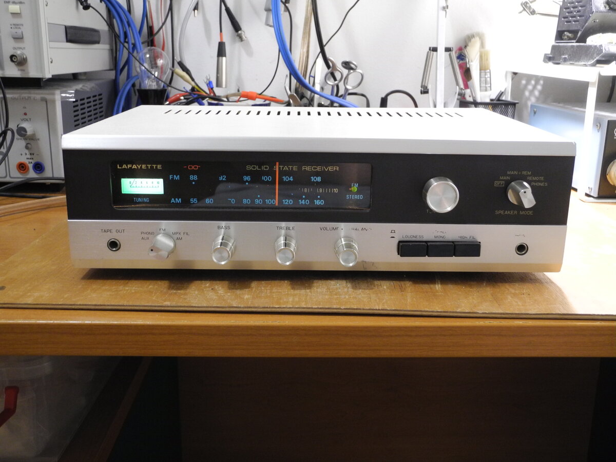
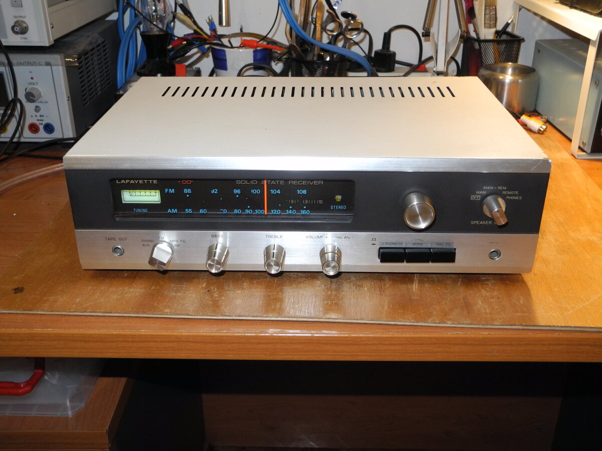
Lafayette LR-100
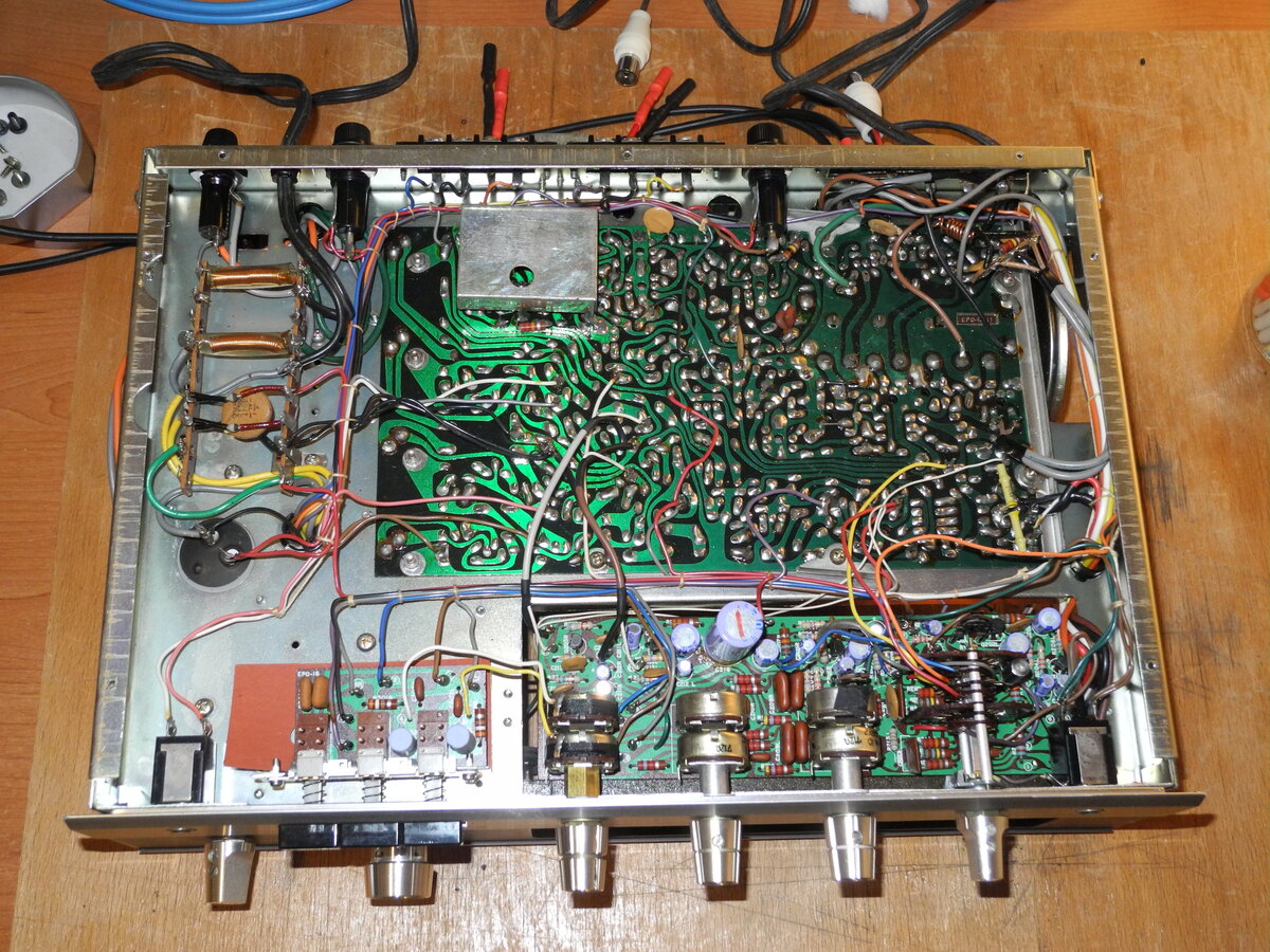
The Lafayette LR-100 is a vintage solid-state stereo receiver from the late 1960s. It uses a fully discrete design with no integrated circuits.
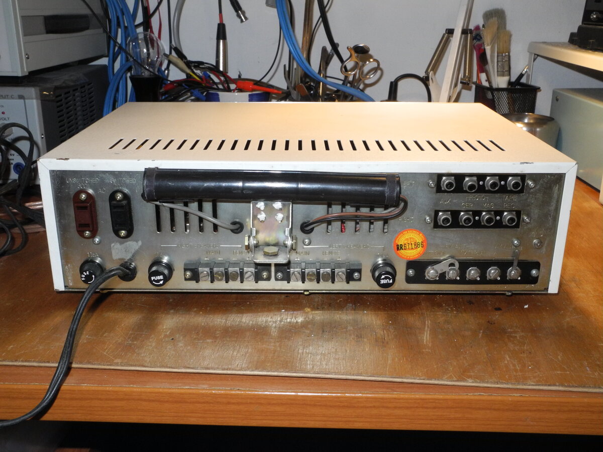
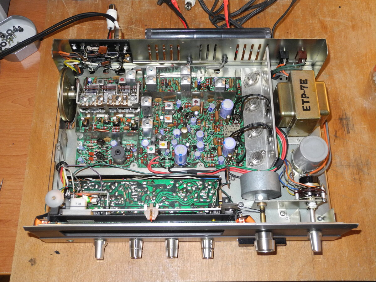
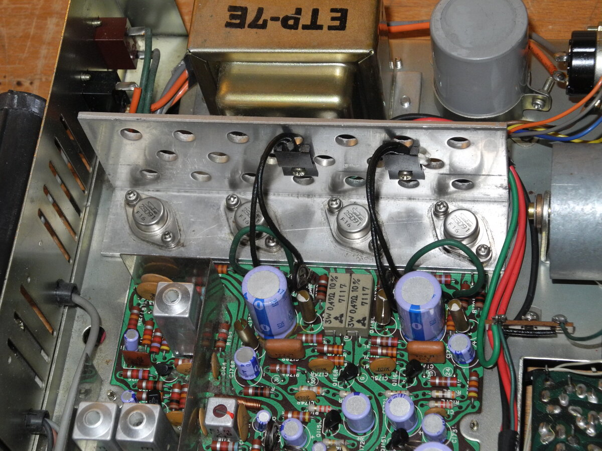
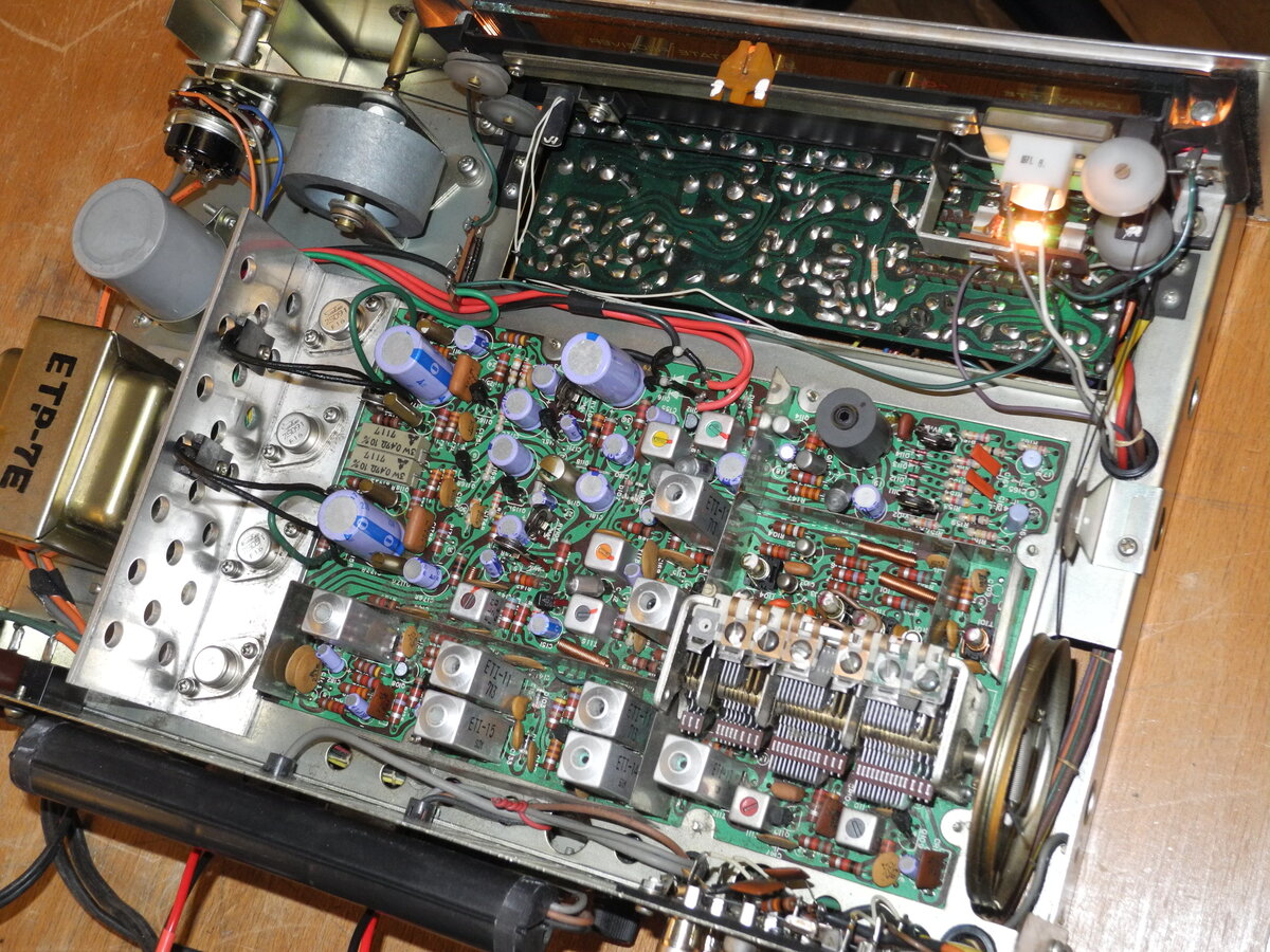
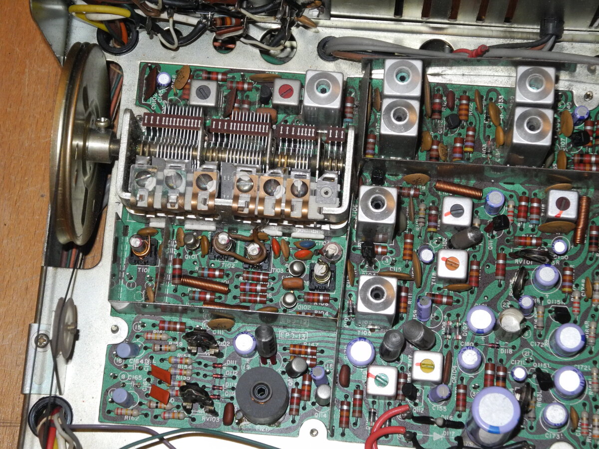
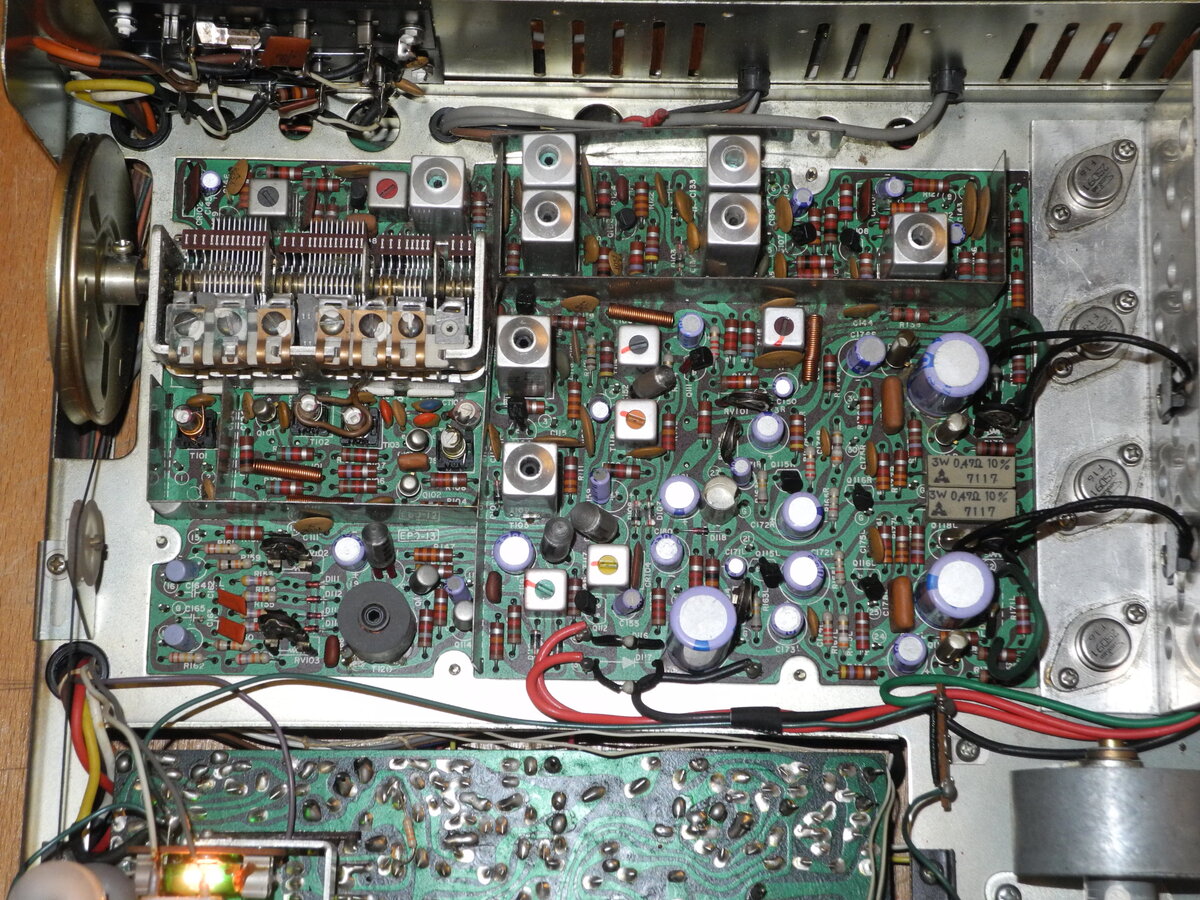
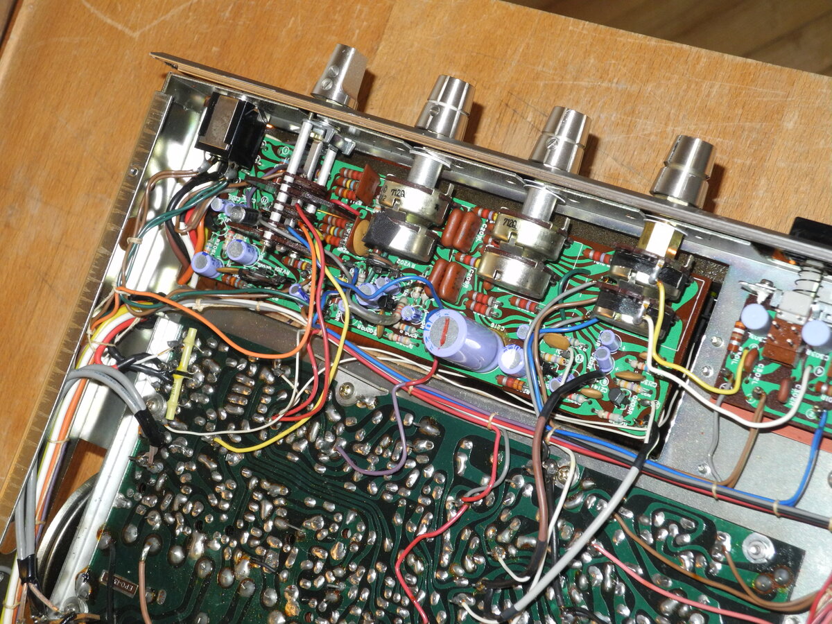
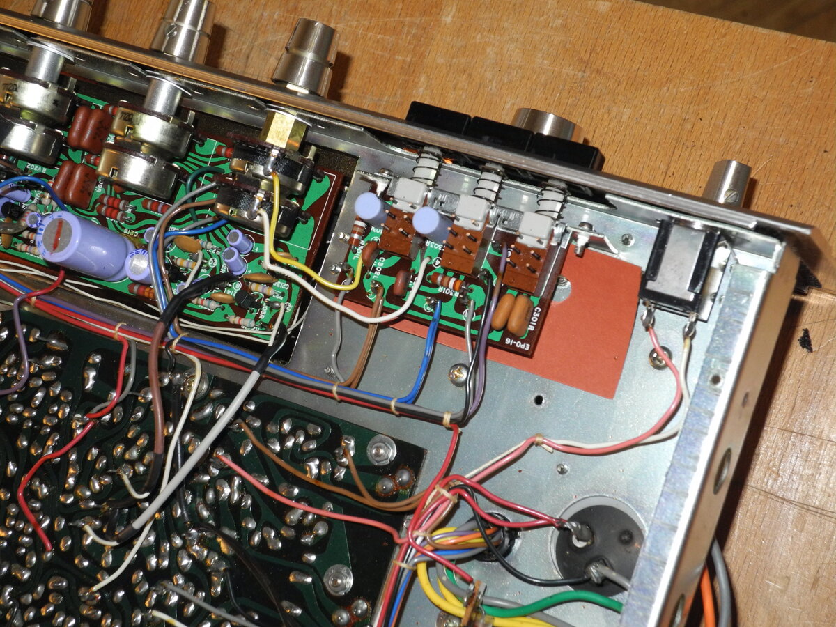
The output stage is based on 2SD91 transistors in a quasi-complementary configuration. Speakers are capacitor-coupled using 470µF capacitors and protected with a fuse. The tuner section uses a 4-gang tuning capacitor.
The build quality is very good, with a faceplate styling typical of 1960s receivers.
Manufacturer: Lafayette
Status: Defunct company
Source: Wikipedia (Lafayette)
General Specifications
Maximum power (4Ω): 20WFrequency response (±1.5dB): 20Hz-50kHz
THD+N: 1.0%
Signal to noise ratio (Line): 75dB
Signal to noise ratio (Phono): 60dB
Input sensitivity (Line): 250mV
Input sensitivity (Phono): 2.3mV
Speaker load impedance: 4Ω-16Ω
Dimensions (WHD): 368×114×267mm
Weight: 6.8kg
Produced: 1968-1970
Initial price: $120
Measured Values
Maximum power (8Ω): 8WFrequency response (20Hz-20kHz): <3.0dB
Channel imbalance: <0.5dB
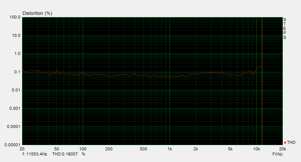
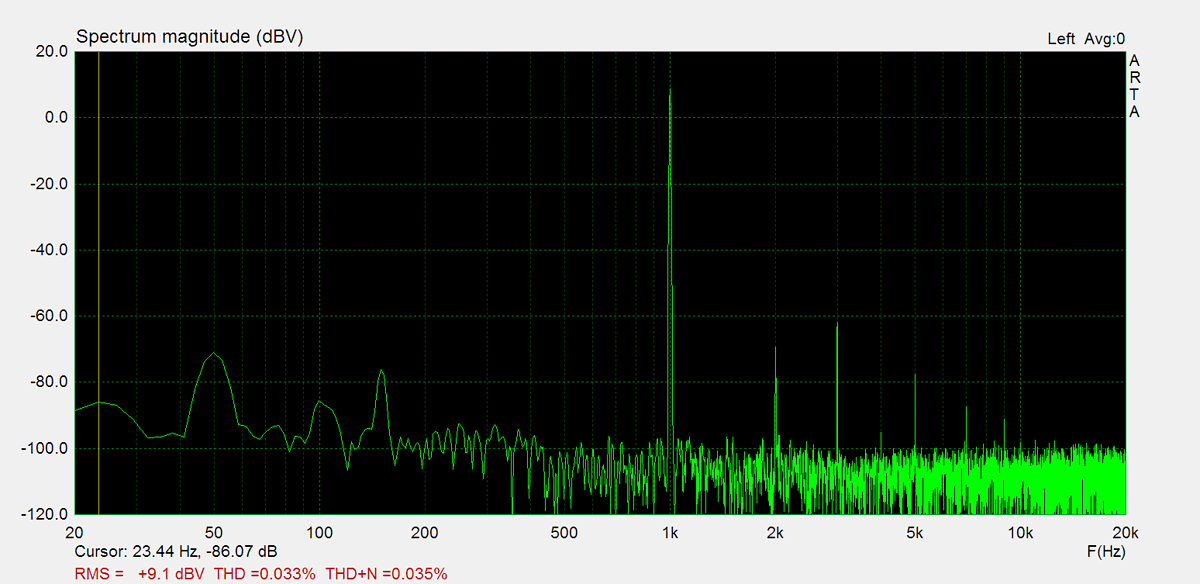
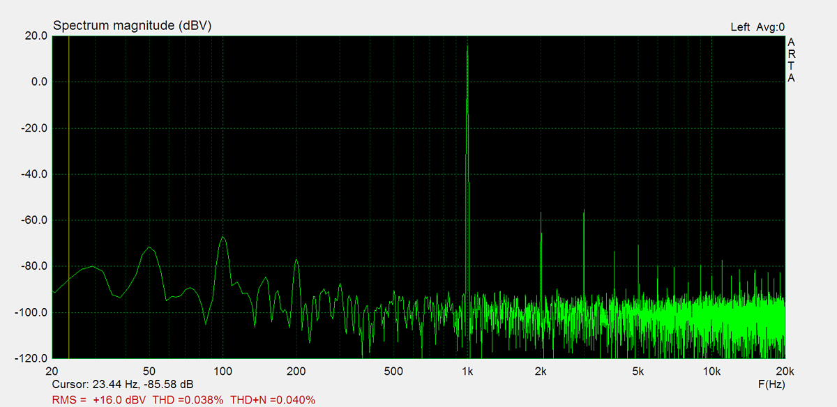
THD (1kHz, 1W): 0.033%
THD+N (1kHz, 1W): 0.035%
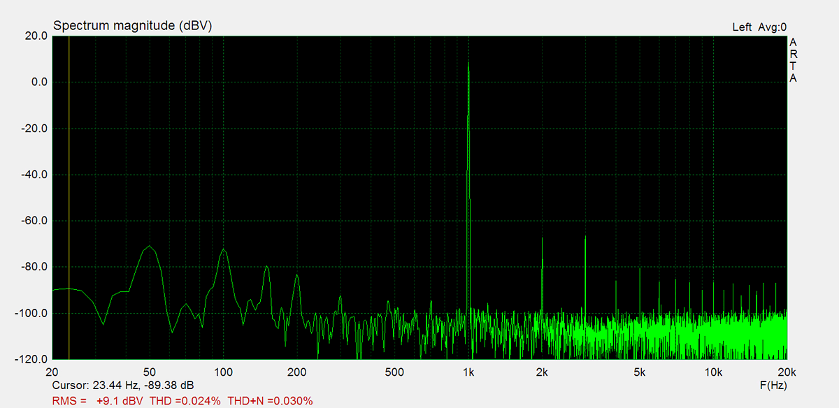
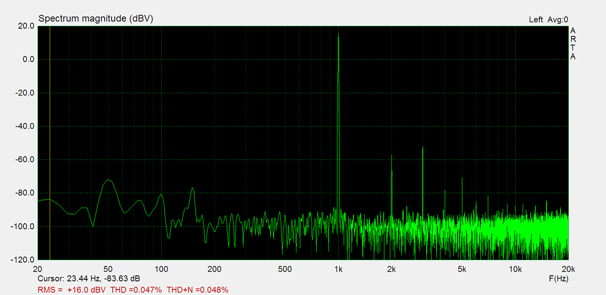
THD (1kHz, 5W): 0.047%
THD+N (1kHz, 5W): 0.048%
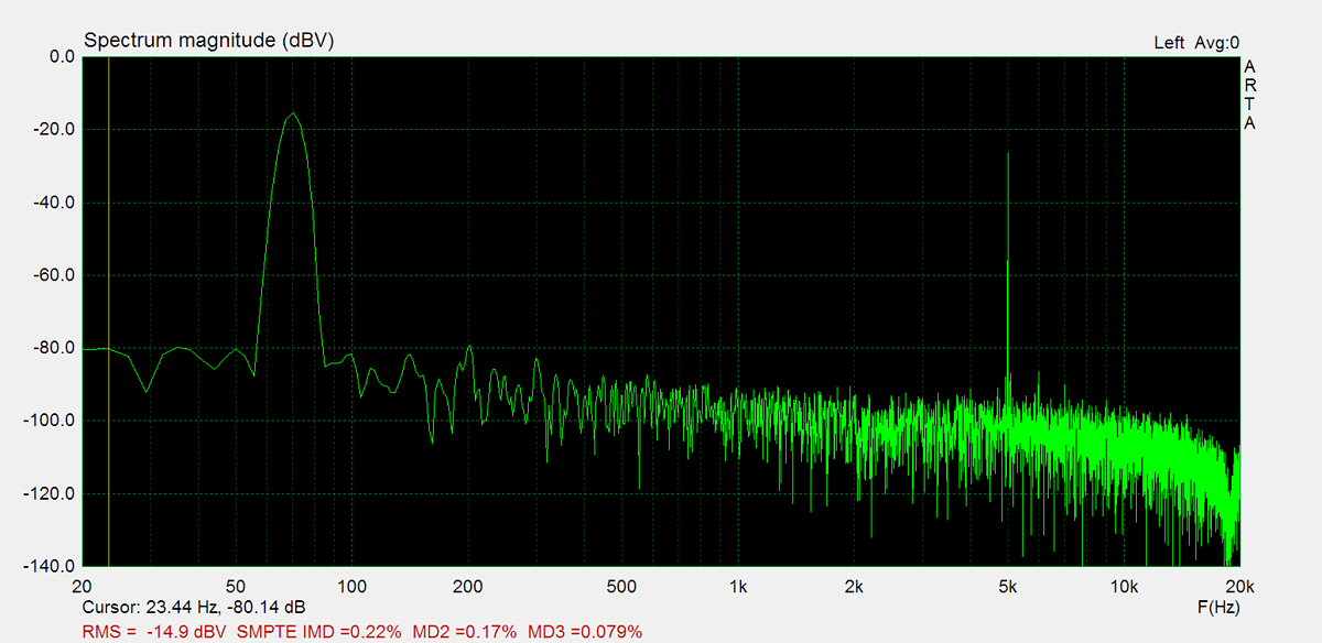
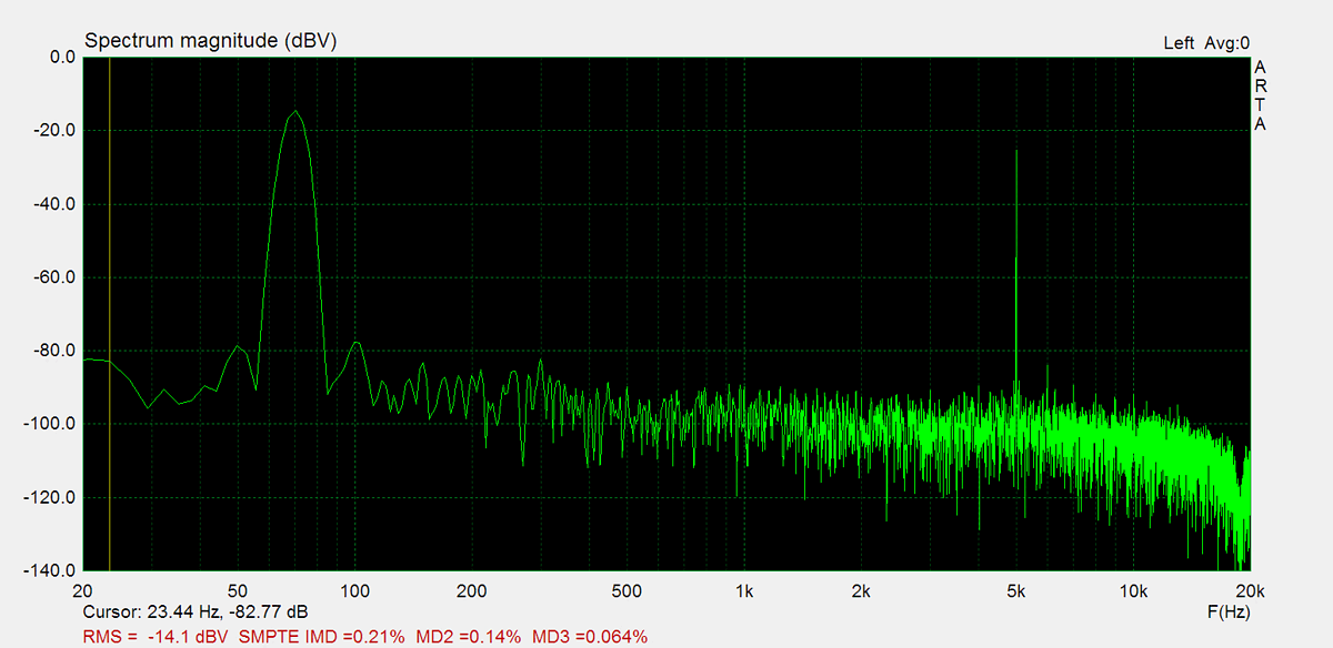
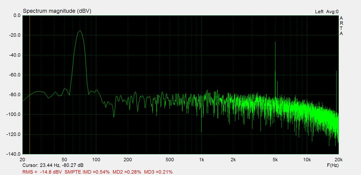
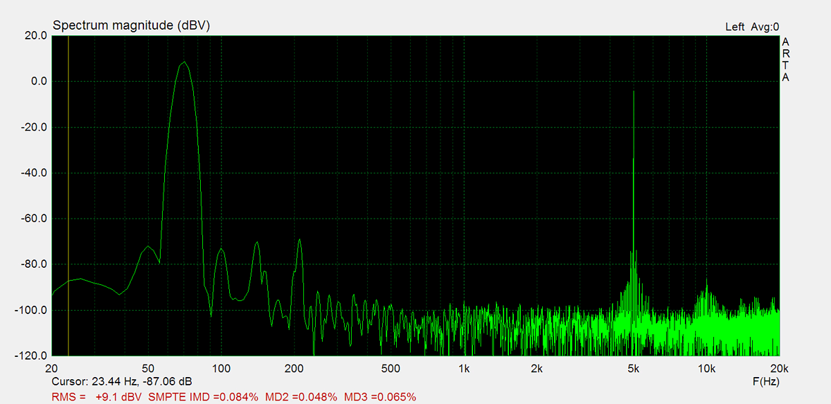
IMD (70Hz, 5kHz, 1W): 0.15%
Noise: -54.2dB
Amplification: 47.3
DC offset L: 0mV
DC offset R: 0mV
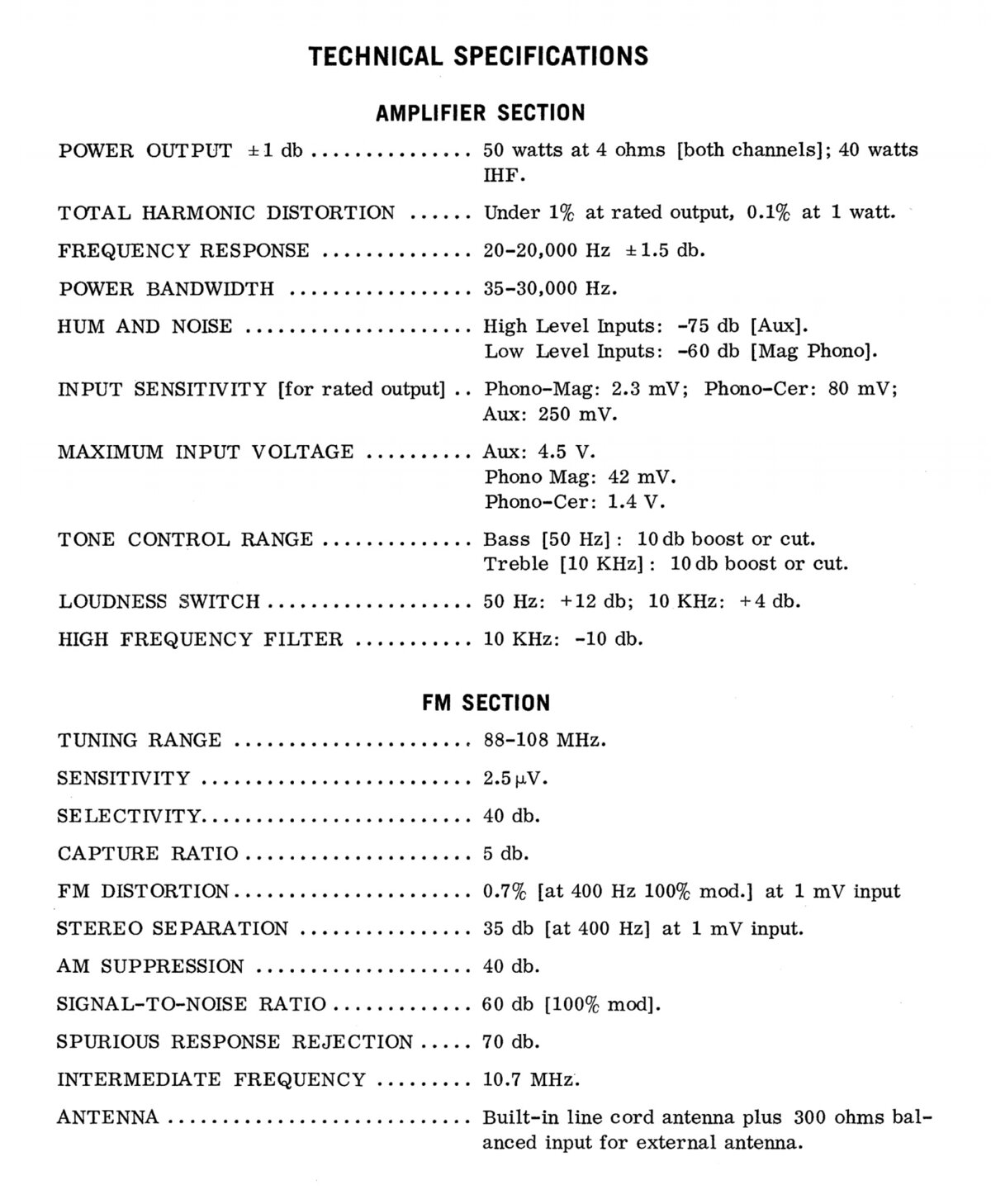
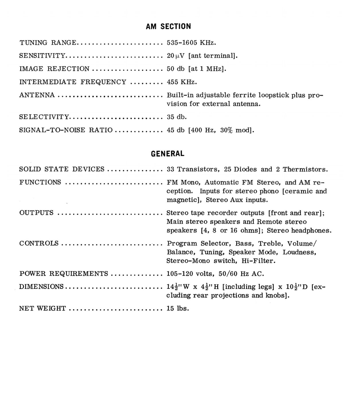
Factory Specification Sheet
Factory specification images are sourced directly from the device's original service manual or user manual. These documents are produced by the manufacturer and provide authoritative information on the product's specifications.
Maximum Power
Maximum power is measured using 8Ω resistors on both channels. A 1kHz sine wave input signal is applied and gradually increased until higher harmonics rise significantly. Typically, this is the point at which output clipping occurs.

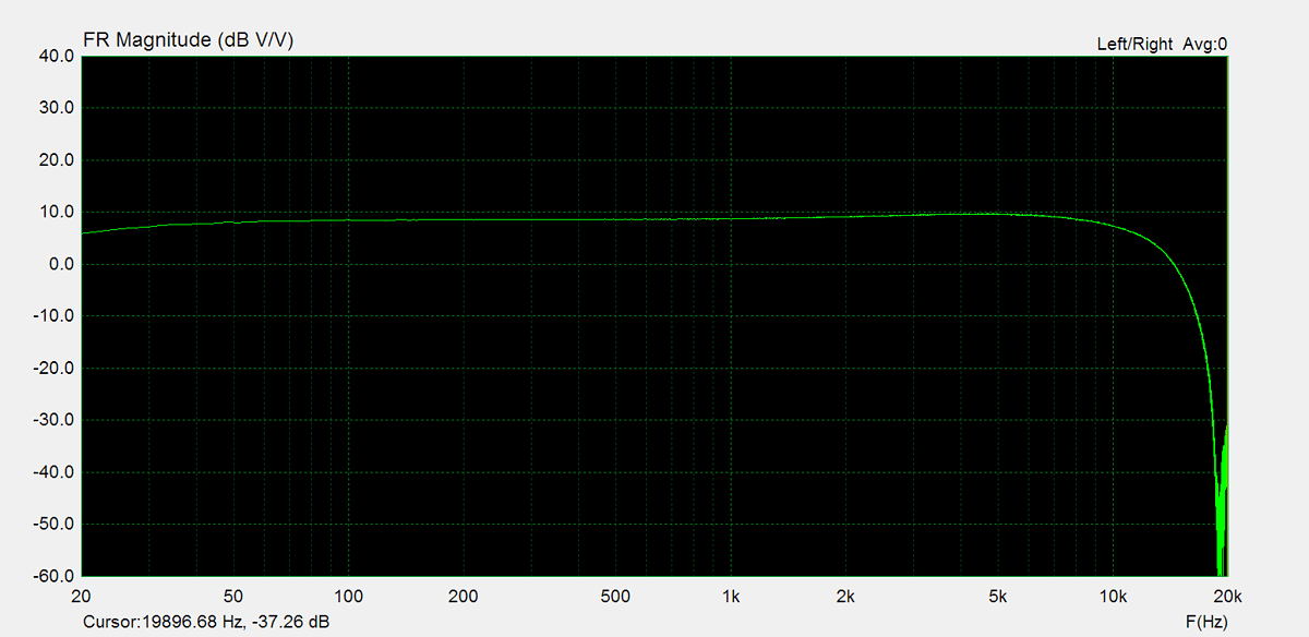
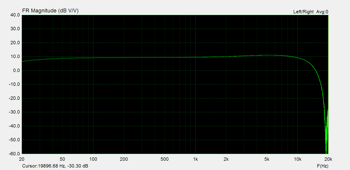
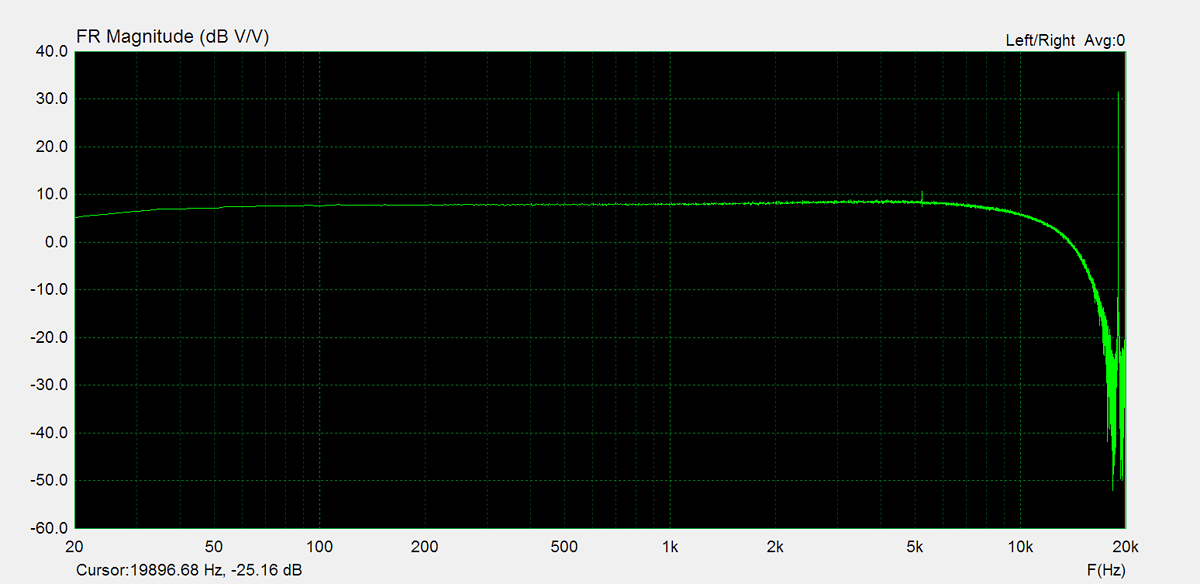
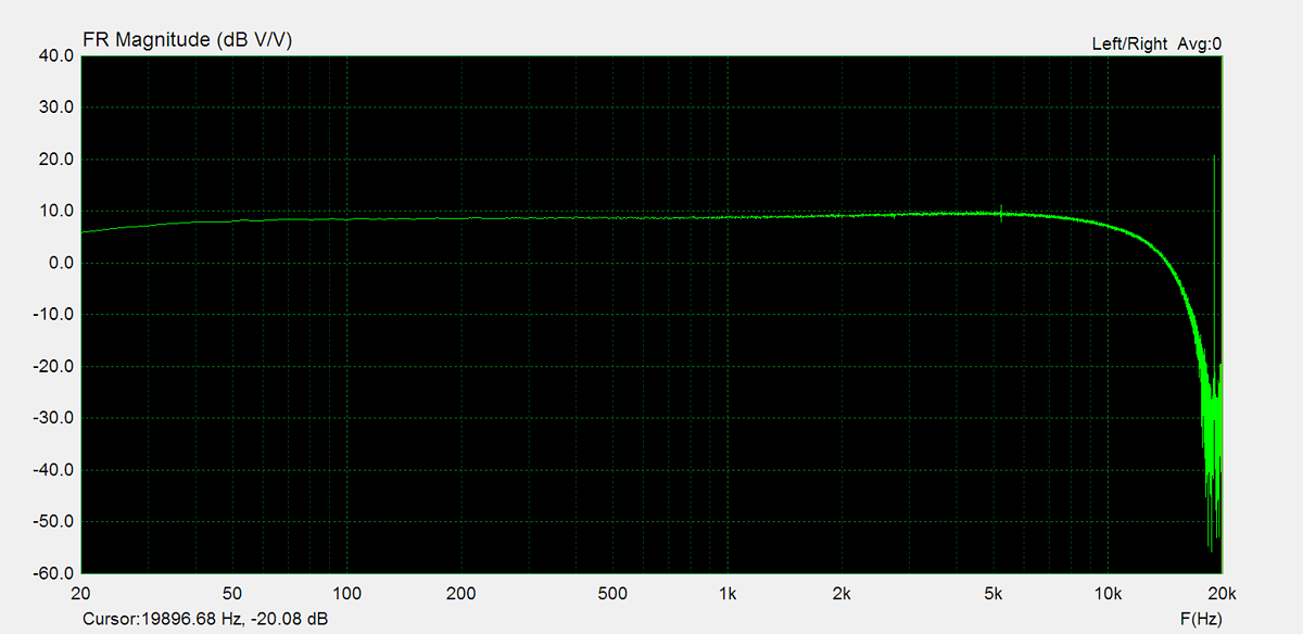
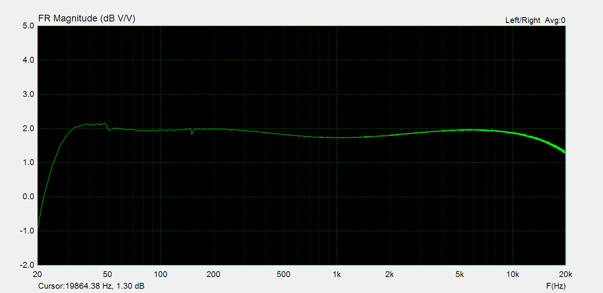
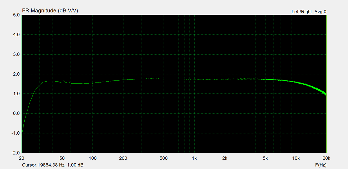
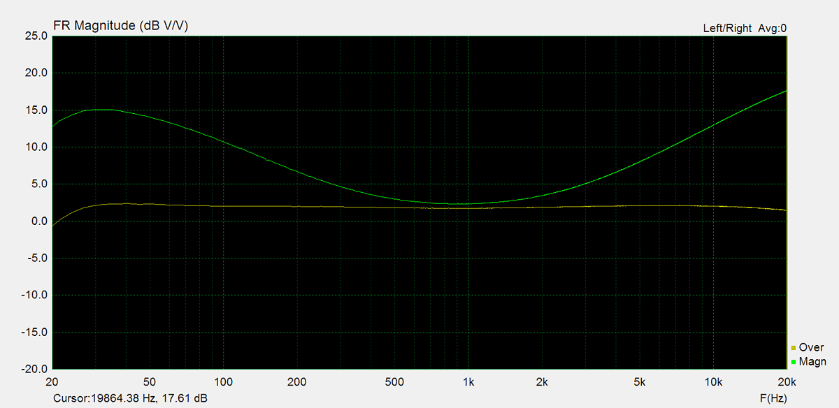
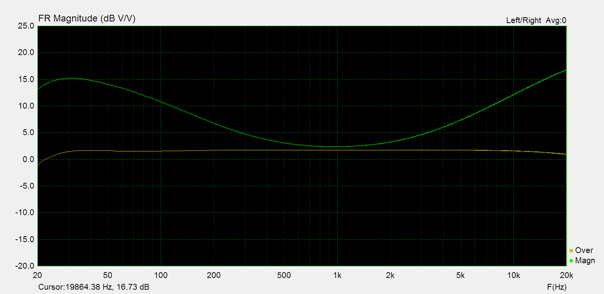
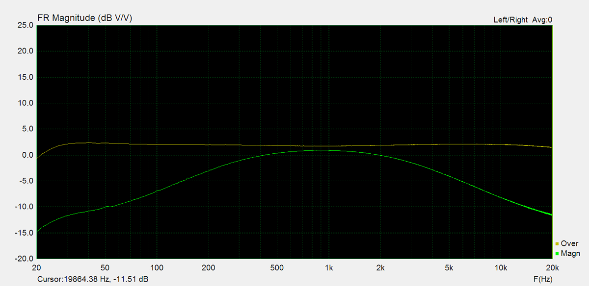
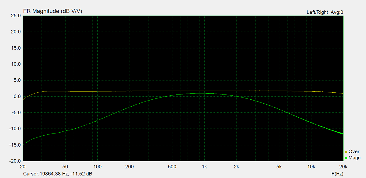
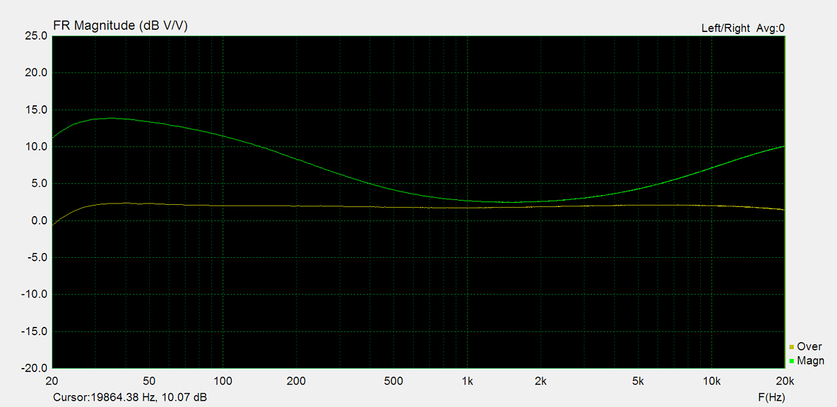
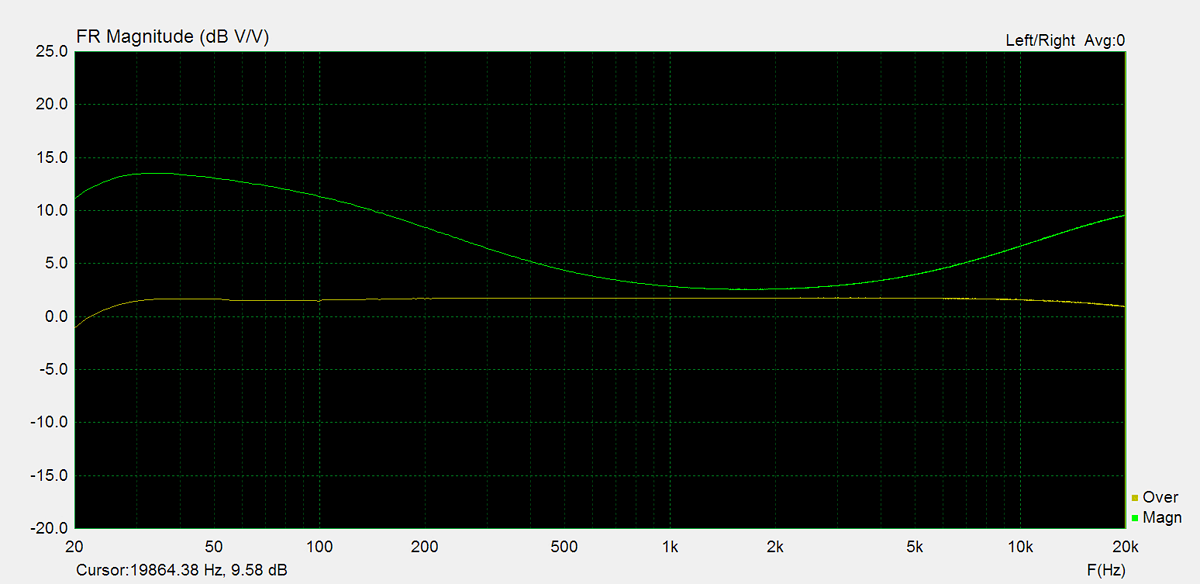
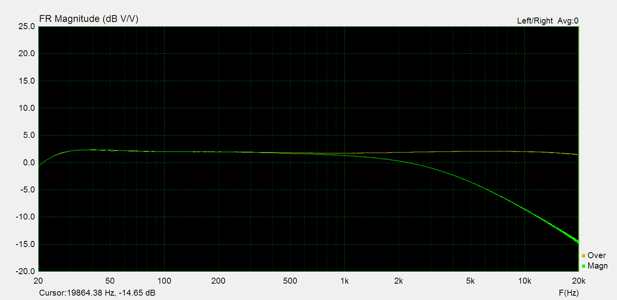
Frequency Response
Frequency response is measured using several equilizer settings. 'Flat' indicates the tone controls are either turned off or set to their neutral position. 'Max' and 'Min' refer to the maximum and minimum tone control positions, respectively. In the phono section, the expected response follows the RIAA equalization curve.

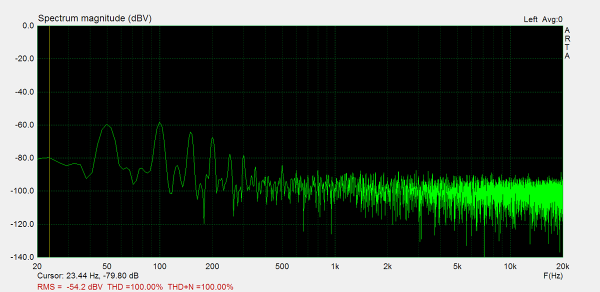
Residual Noise
These graphs display the noise levels at various volume positions. To eliminate any interference from the input signal, the input lines are shorted during the measurement. Generally, the noise is highest at the mid-point of the volume range (50%)


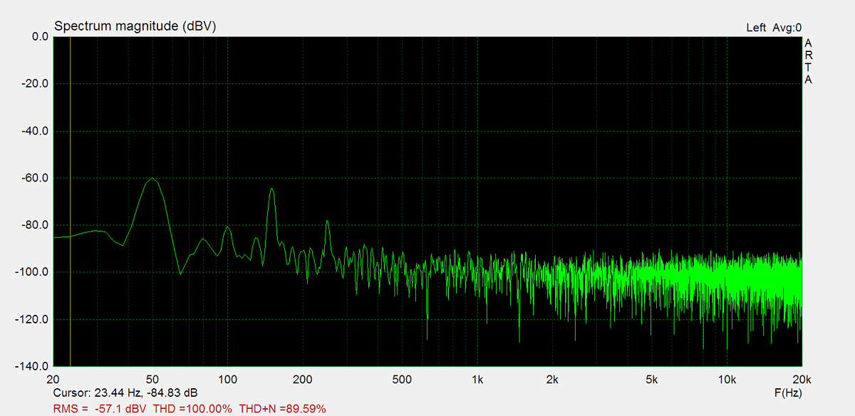
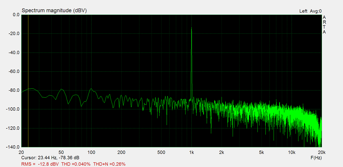
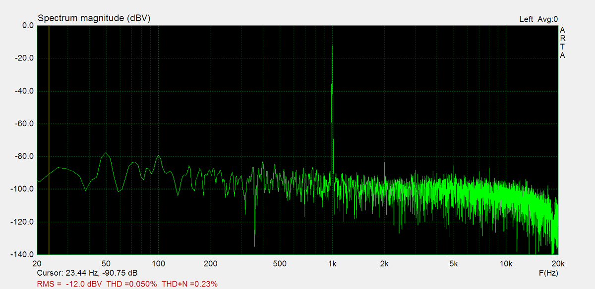
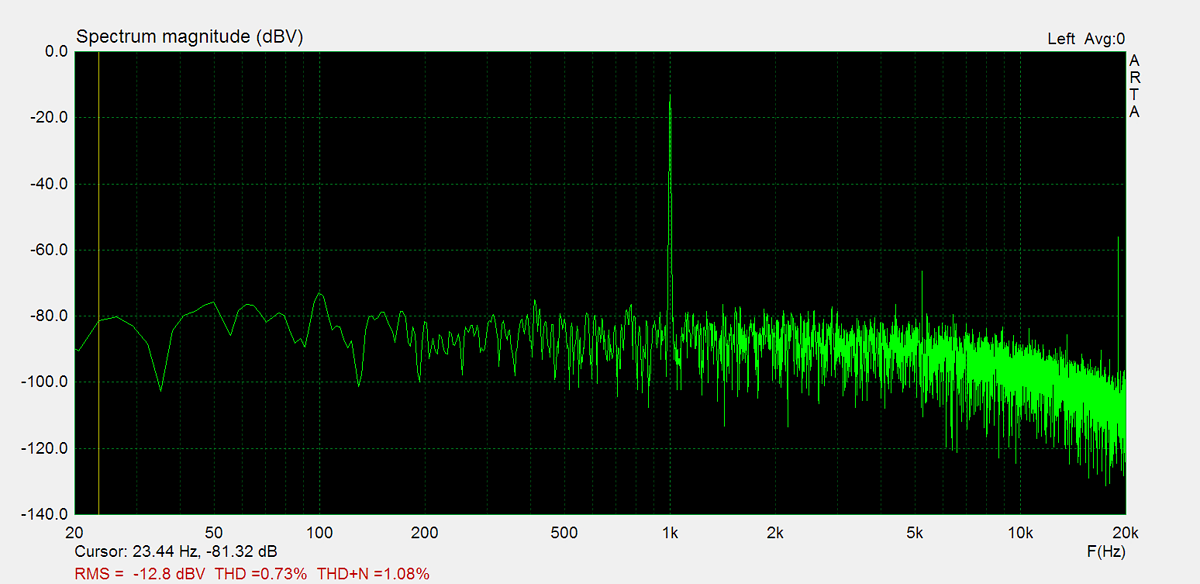
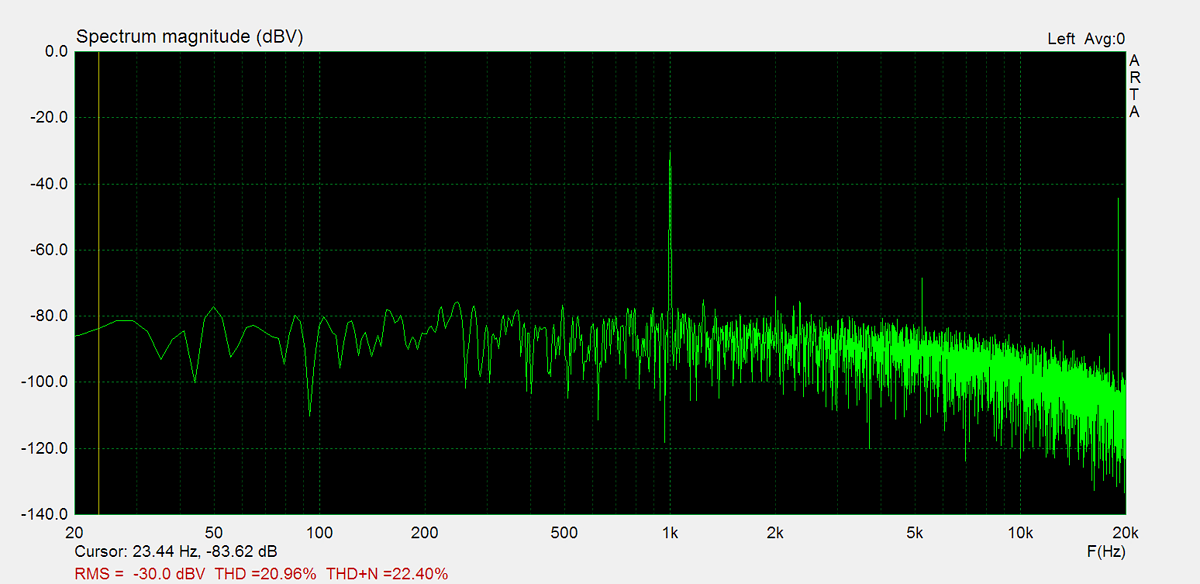
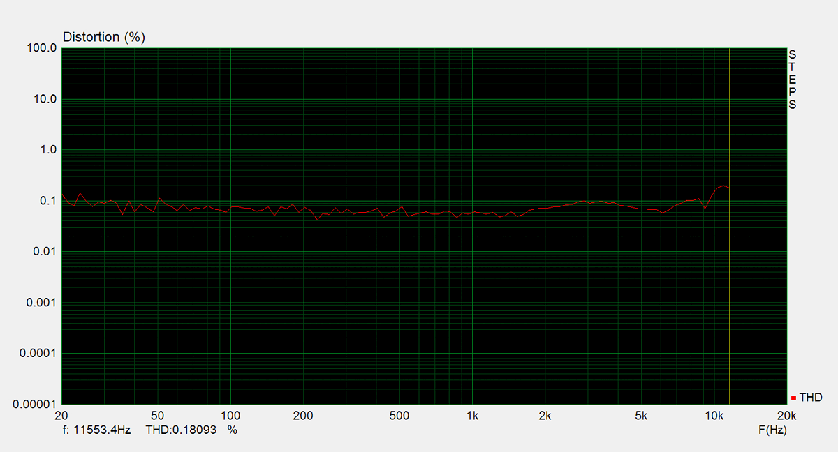
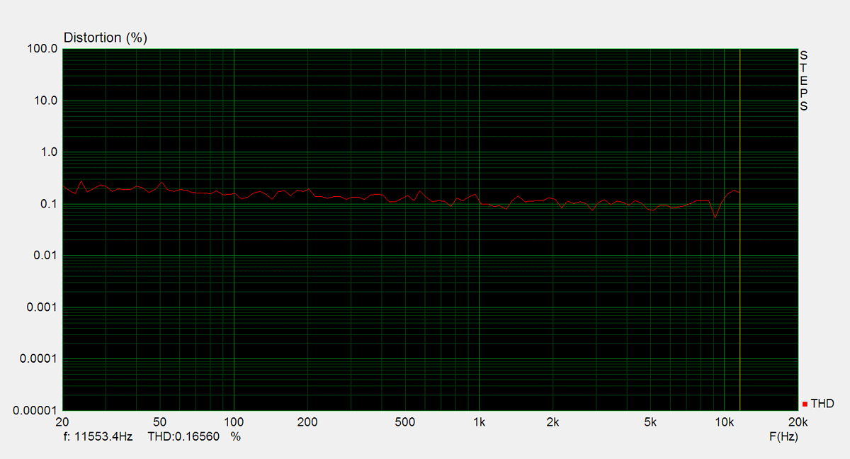
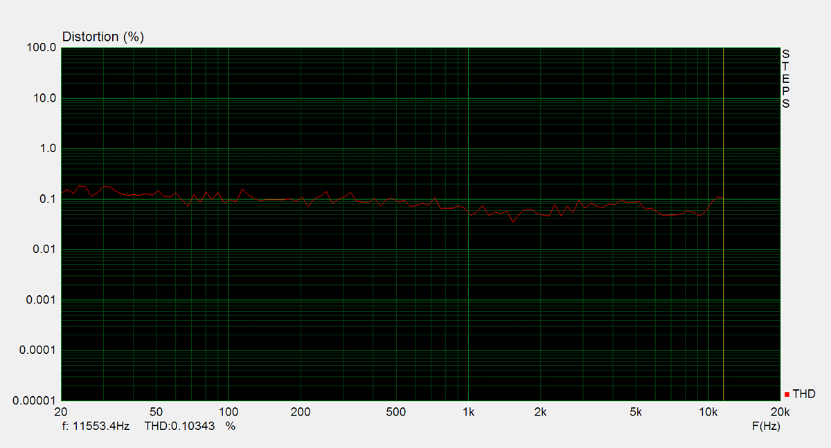
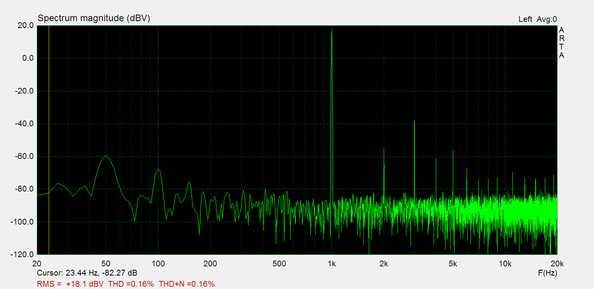
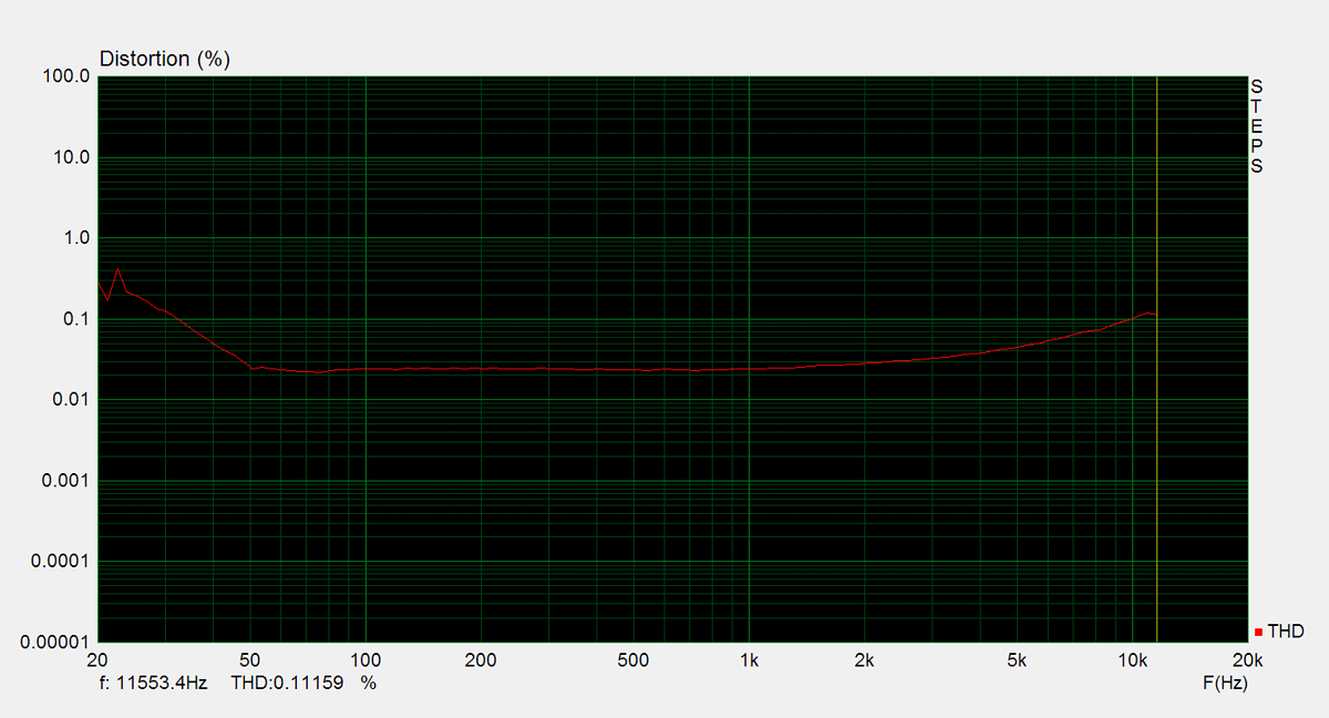
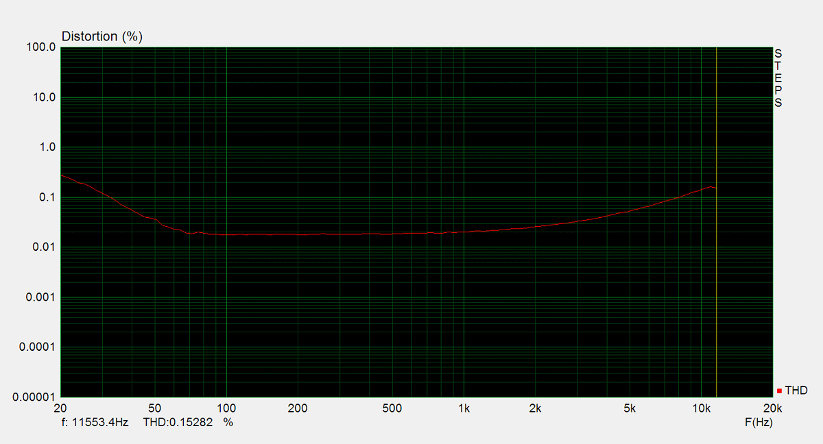
Distorsion
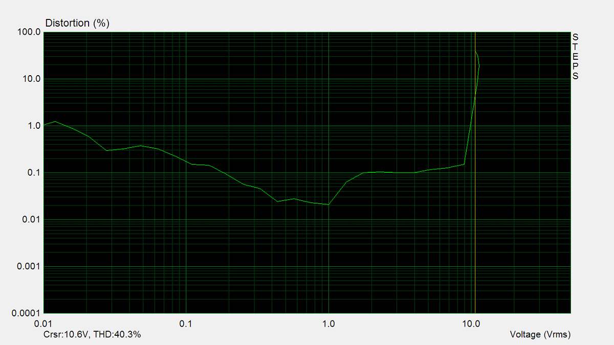
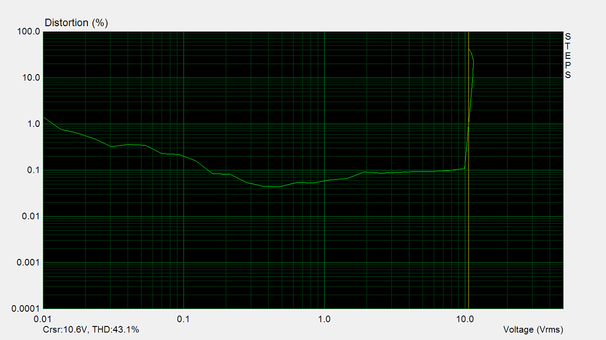
Total harmonic distortion (THD) is measured using a 1kHz sine wave input, with the output level adjusted to meet different conditions. Intermodulation distortion (IMD) is measured using 'two sine' input signal. THD versus voltage is measured with a 1kHz sine wave input, while THD versus frequency is measured at various output levels.

FM Tuner
Measurements of the tuner section were performed using an FM signal generator, with its output fed directly into the antenna input. AM measurements were not conducted.