Marantz 2215BL
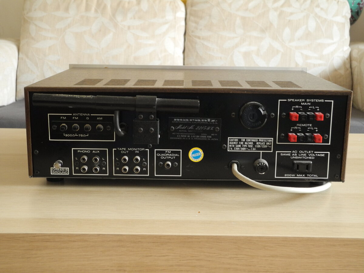
The Marantz 2215BL is a classic stereo receiver from the mid 1970s. It belongs to the second generation of Marantz 22xx receivers. The L variant was designed for the European market and includes Long Wave tuning and multi-voltage support, making it distinct from the US-market 2215B.
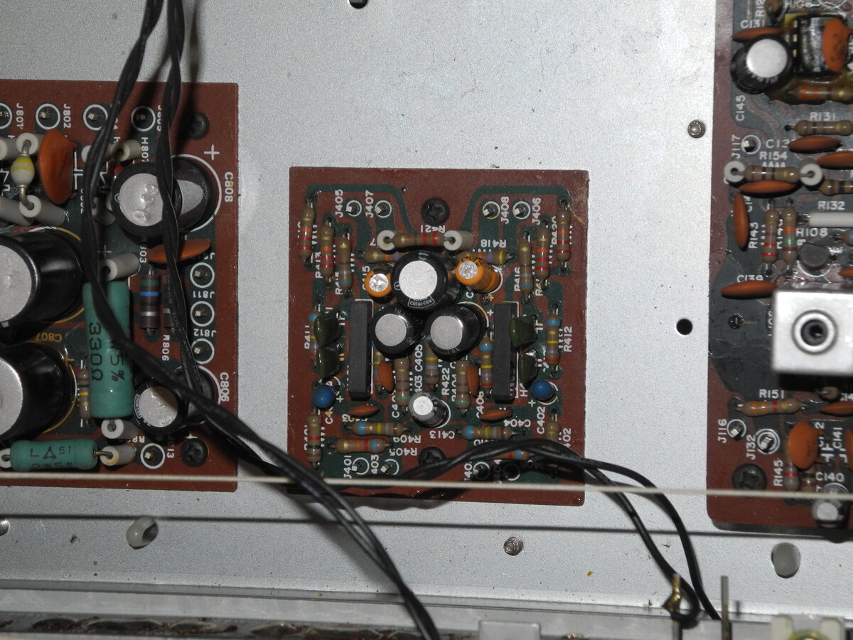
The power amplifier is built using a single-rail power supply, filtered by a 3300µF capacitor. Output transistors are 2SD313 and 2SB507. A specific 6V IN1006035 bulb is used in the amplifier circuit as a non-linear resistor. The speakers are connected via 2200µF output coupling capacitors. Two pairs of speakers are supported, and there is no protection relay.
The tuner section features a 3-gang FM tuning capacitor, a discrete FM discriminator stage, and an HA1156 stereo decoder.
Compact and elegant, the 2215BL represents an accessible entry into vintage Marantz hi-fi.
Manufacturer: Marantz
Status: Active company
Official website: marantz.com


General Specifications
Maximum power (8Ω): 15WFrequency response (±1.5dB): 20Hz-60kHz
Frequency response (±0.5dB): 40Hz-20kHz
THD: 0.8%
IMD: 0.8%
Signal to noise ratio (Line): 85dB
Signal to noise ratio (Phono): 74dB
Input sensitivity (Line): 150mV
Input sensitivity (Phono): 2.2mV
Damping factor: 40
Speaker load impedance: 8Ω-16Ω
Dimensions (WHD): 441×137×292mm
Weight: 9.5kg
Produced: 1973-1977
Initial price: $250
Measured Values
Maximum power (8Ω): 15WFrequency response (20Hz-20kHz): <1.0dB
Channel imbalance: <0.5dB
THD (1kHz, 1W): 0.053%
THD+N (1kHz, 1W): 0.066%
THD (1kHz, 10W): 0.11%
THD+N (1kHz, 10W): 0.11%
IMD (70Hz, 5kHz, 1W): 0.17%
Noise: -58.5dB
Amplification: 72.4
DC offset L: 0mV
DC offset R: 0mV
Factory Specification Sheet
Factory specification images are sourced directly from the device's original service manual or user manual. These documents are produced by the manufacturer and provide authoritative information on the product's specifications.
Maximum Power
Maximum power is measured using 8Ω resistors on both channels. A 1kHz sine wave input signal is applied and gradually increased until higher harmonics rise significantly. Typically, this is the point at which output clipping occurs.


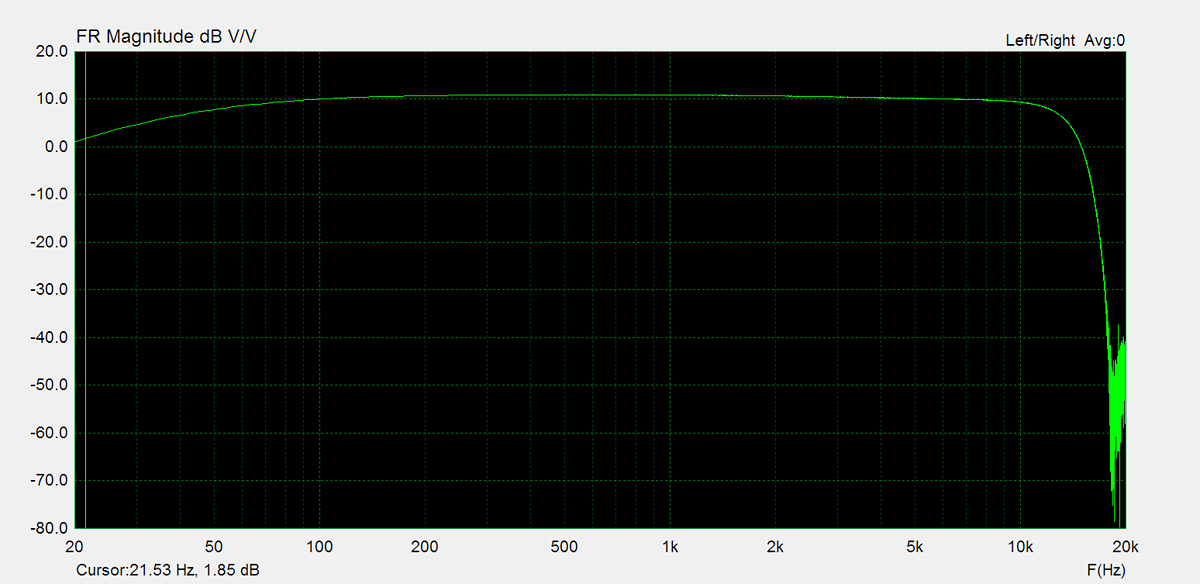
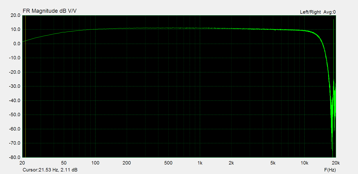
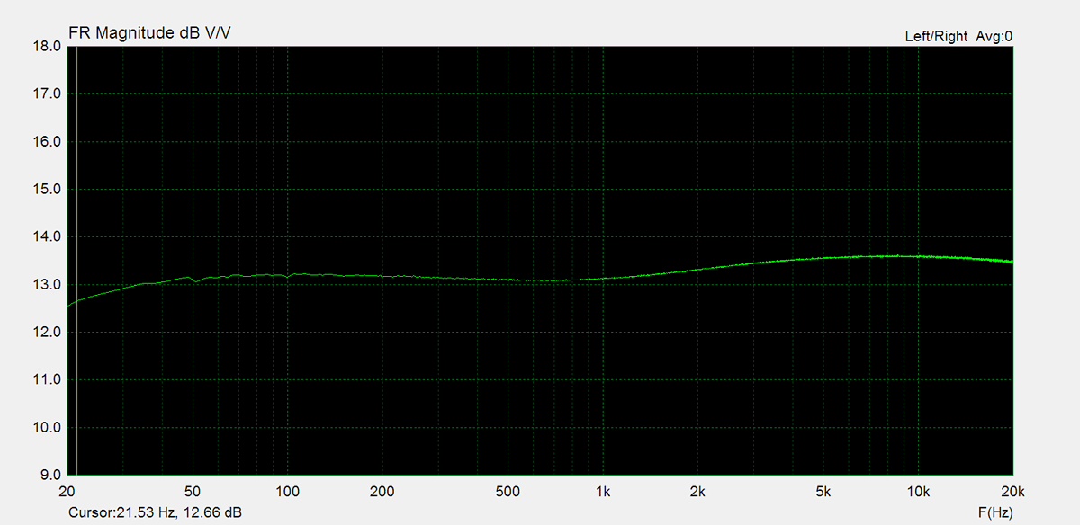
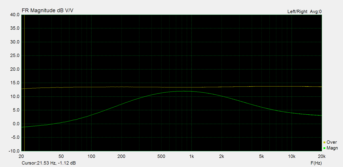
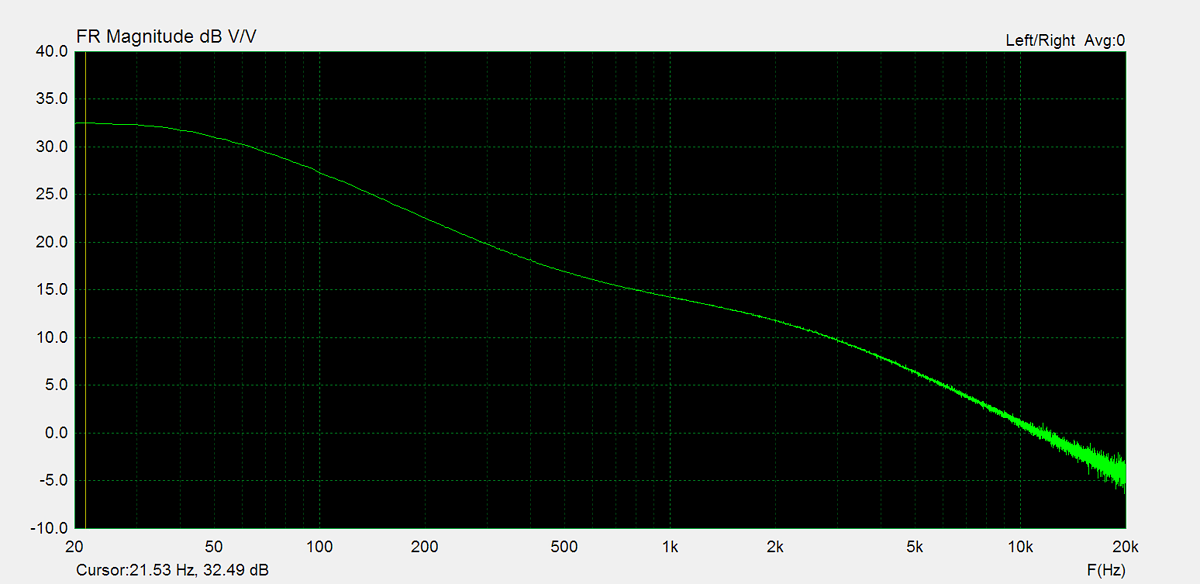
Frequency Response
Frequency response is measured using several equilizer settings. 'Flat' indicates the tone controls are either turned off or set to their neutral position. 'Max' and 'Min' refer to the maximum and minimum tone control positions, respectively. In the phono section, the expected response follows the RIAA equalization curve.


Residual Noise
These graphs display the noise levels at various volume positions. To eliminate any interference from the input signal, the input lines are shorted during the measurement. Generally, the noise is highest at the mid-point of the volume range (50%)


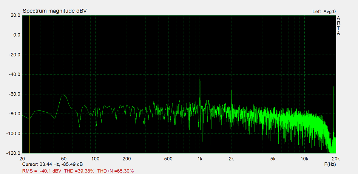
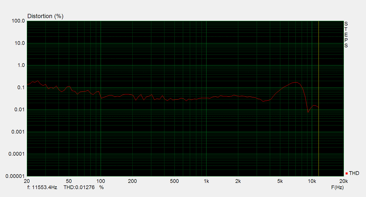
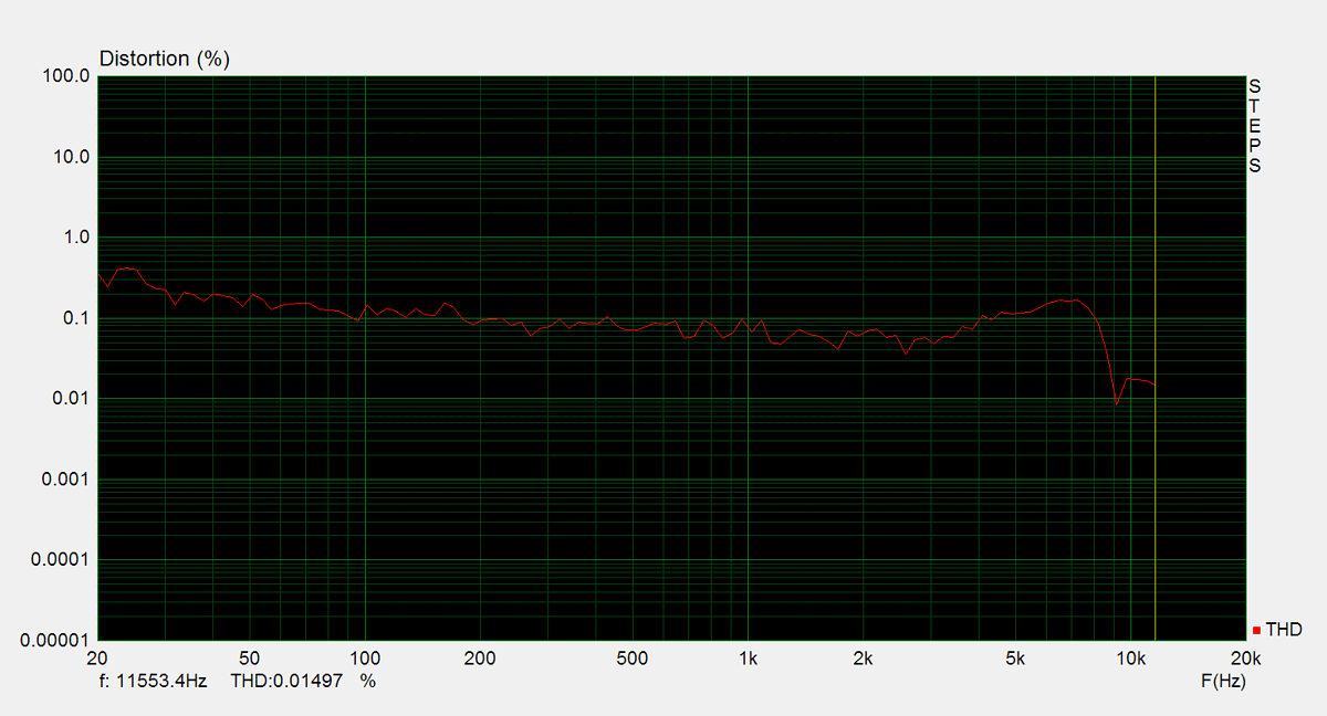
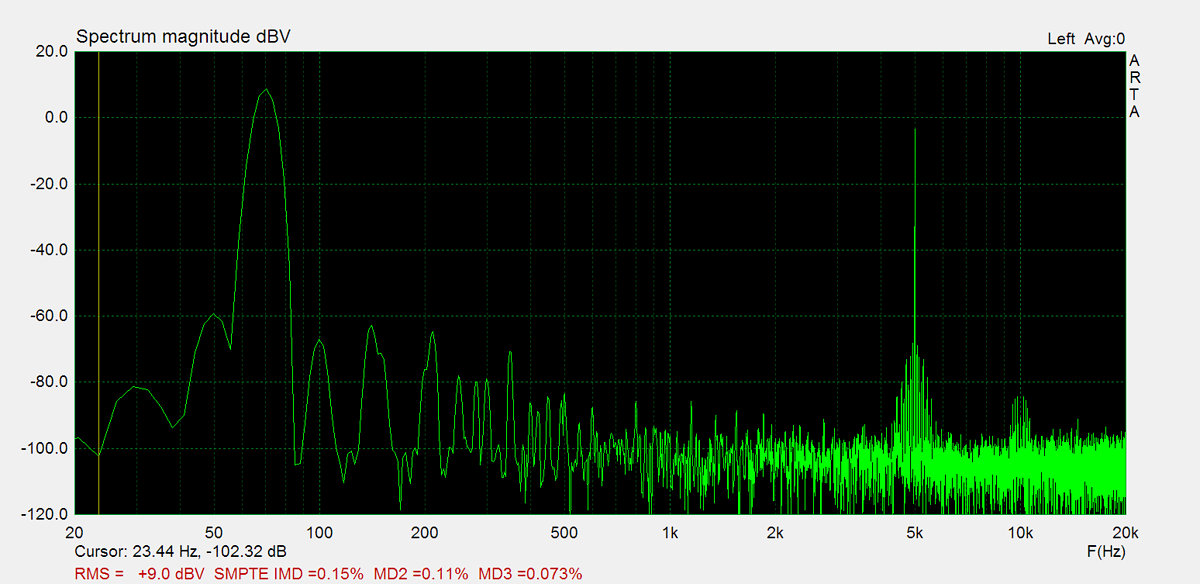
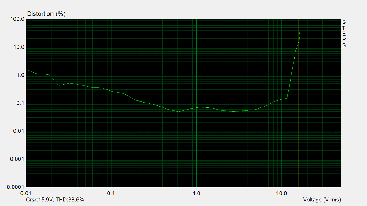
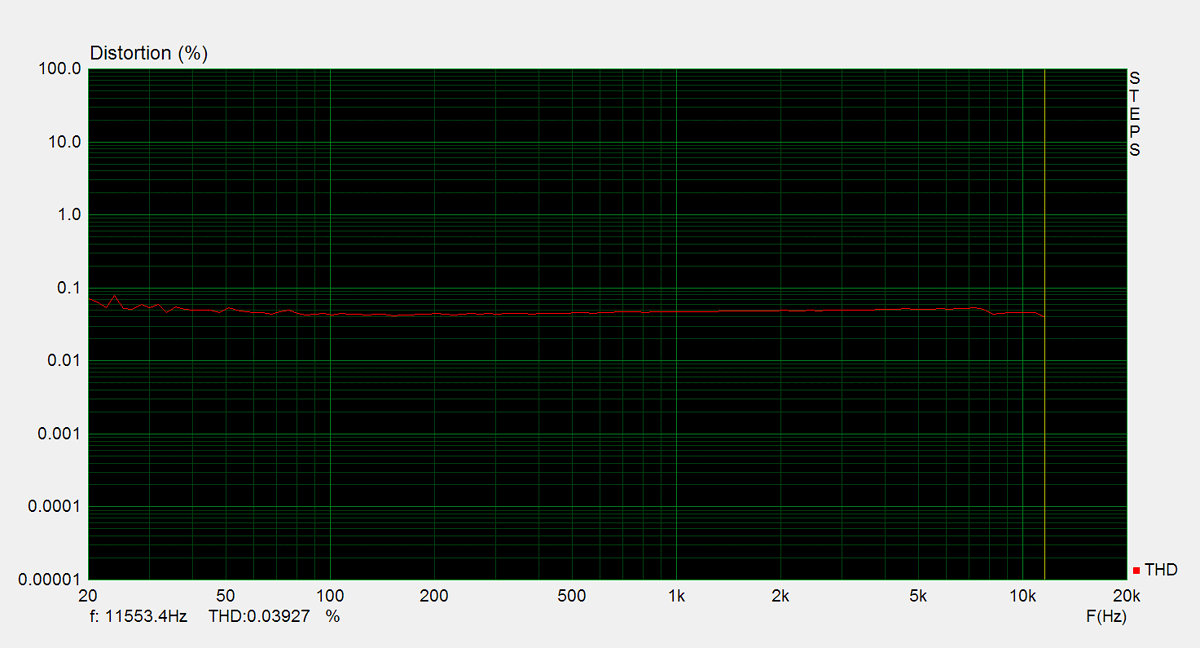
Distorsion
Total harmonic distortion (THD) is measured using a 1kHz sine wave input, with the output level adjusted to meet different conditions. Intermodulation distortion (IMD) is measured using 'two sine' input signal. THD versus voltage is measured with a 1kHz sine wave input, while THD versus frequency is measured at various output levels.


FM Tuner
Measurements of the tuner section were performed using an FM signal generator, with its output fed directly into the antenna input. AM measurements were not conducted.