
Pioneer SX-590
The Pioneer SX-590 is a stereo receiver from Pioneer's popular SX series, produced during the late 1970s and aimed at entry-level to mid-range hi-fi users. It combines a silver faceplate with a black scale, creating the distinctive SX-series look.
The amplifier section is based on STK0029 modules and is supported by two 6800µF filter capacitors in the power supply. Two pair of speakers are supported, but there is no relay-based protection circuit.
The FM tuner section features a 3-gang tuning capacitor and uses the PA3001 FM discriminator together with the PA1001 stereo decoder IC, providing good reception and satisfying stereo performance.
The internal construction is simple and well organized, with accessible components that make servicing easier. The soundstage is warm and clean, reflecting the typical Pioneer sound signature from this period.
Manufacturer: Pioneer
Status: Active company
Official website: global.pioneer


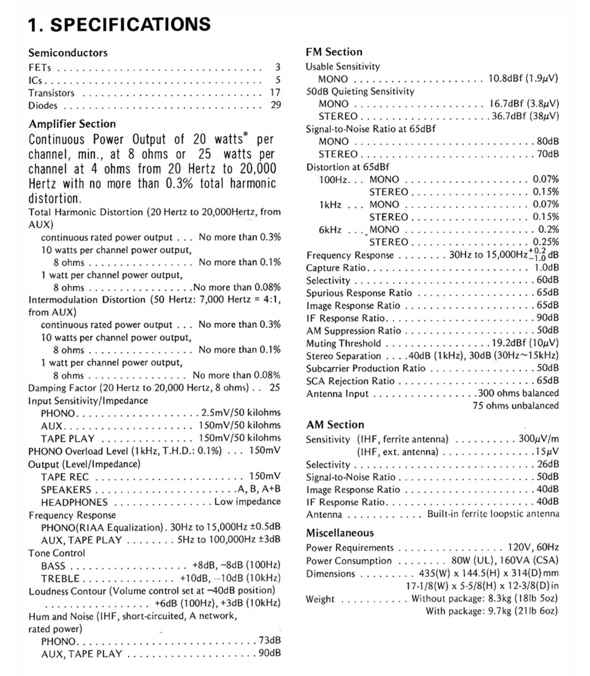
General Specifications
Maximum power (8Ω): 20WMaximum power (4Ω): 25W
Frequency response (-3dB): 5Hz-100kHz
THD: 0.3%
Signal to noise ratio (Line): 90dB
Signal to noise ratio (Phono): 73dB
Input sensitivity (Line): 200mV
Input sensitivity (Phono): 2.5mV
Damping factor: 25
Speaker load impedance: 4Ω-16Ω
Dimensions (WHD): 435×145×314mm
Weight: 8.3kg
Produced: 1979-1980
Initial price: 660DM
Measured Values
Maximum power (8Ω): 22WFrequency response (20Hz-20kHz): <1.0dB
Channel imbalance: <1.0dB
THD (1kHz, 1W): 0.028%
THD+N (1kHz, 1W): 0.033%
THD (1kHz, 10W): 0.048%
THD+N (1kHz, 10W): 0.046%
IMD (70Hz, 5kHz, 1W): 0.095%
Noise: -60.3dB
Amplification: 119.9
DC offset L: 91.0mV
DC offset R: 89.0mV
Factory Specification Sheet
Factory specification images are sourced directly from the device's original service manual or user manual. These documents are produced by the manufacturer and provide authoritative information on the product's specifications.
Maximum Power
Maximum power is measured using 8Ω resistors on both channels. A 1kHz sine wave input signal is applied and gradually increased until higher harmonics rise significantly. Typically, this is the point at which output clipping occurs.


Frequency Response
Frequency response is measured using several equilizer settings. 'Flat' indicates the tone controls are either turned off or set to their neutral position. 'Max' and 'Min' refer to the maximum and minimum tone control positions, respectively. In the phono section, the expected response follows the RIAA equalization curve.


Residual Noise
These graphs display the noise levels at various volume positions. To eliminate any interference from the input signal, the input lines are shorted during the measurement. Generally, the noise is highest at the mid-point of the volume range (50%)


Distorsion
Total harmonic distortion (THD) is measured using a 1kHz sine wave input, with the output level adjusted to meet different conditions. Intermodulation distortion (IMD) is measured using 'two sine' input signal. THD versus voltage is measured with a 1kHz sine wave input, while THD versus frequency is measured at various output levels.


FM Tuner
Measurements of the tuner section were performed using an FM signal generator, with its output fed directly into the antenna input. AM measurements were not conducted.


