Sony STR-212L
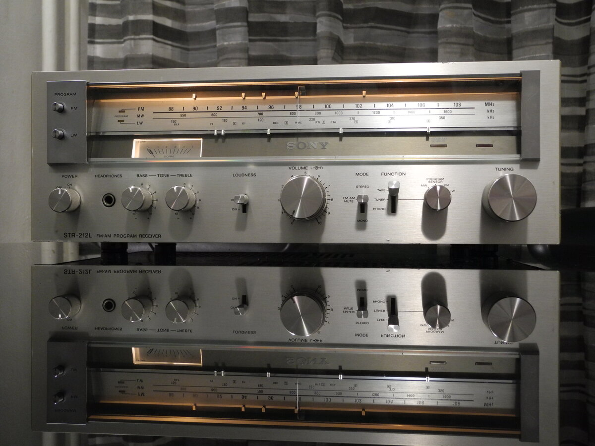
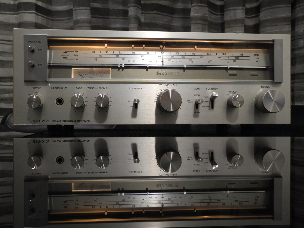
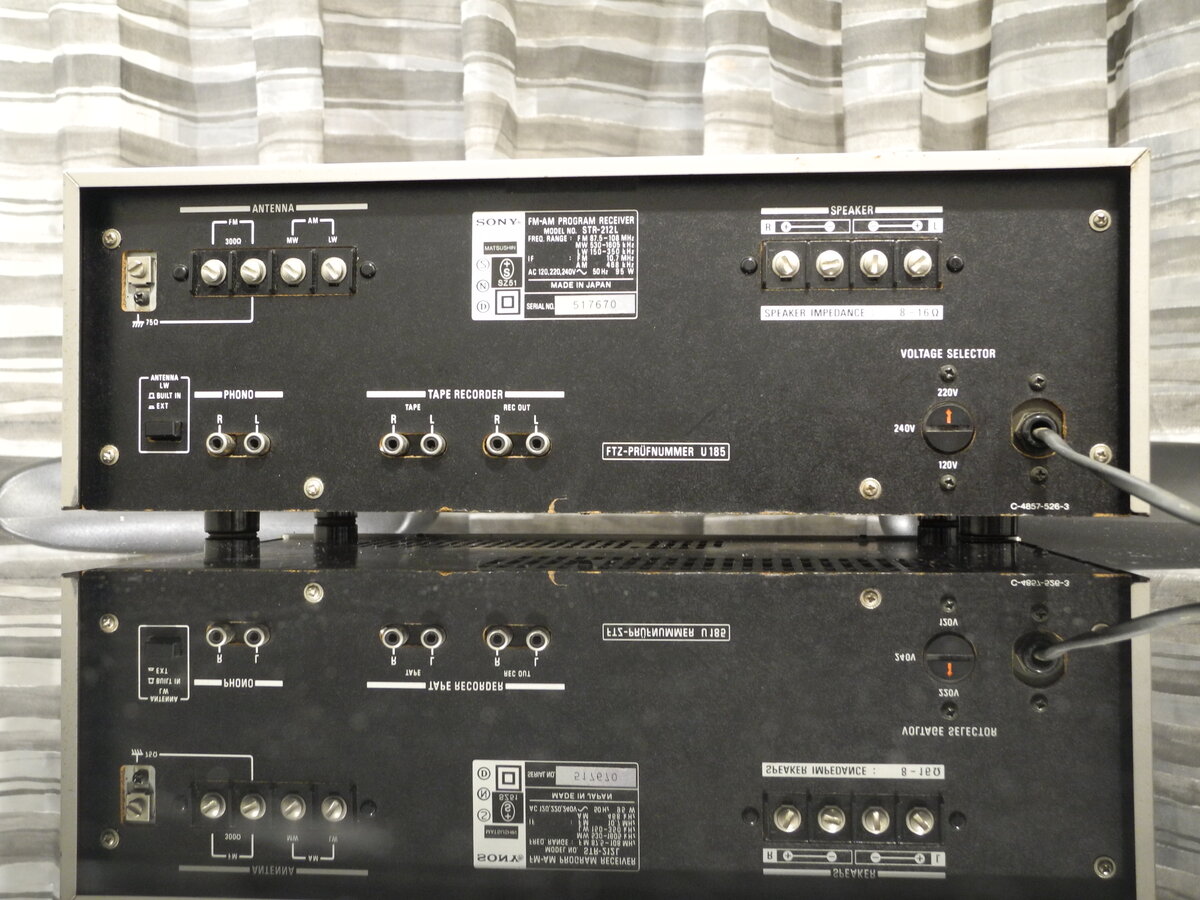
The Sony STR-212L is a stereo receiver from the late 1970s. The L in the model name denotes the European version, which supports the LW band in addition to FM and MW reception.
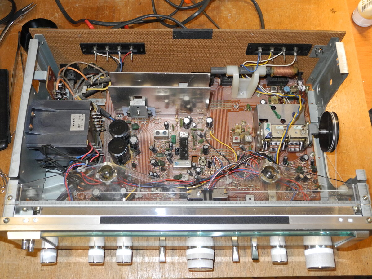
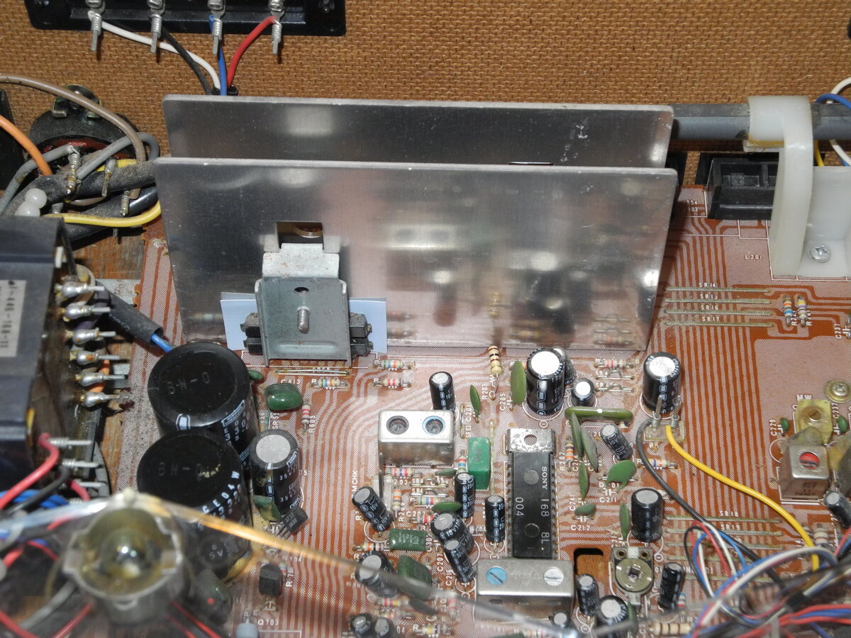
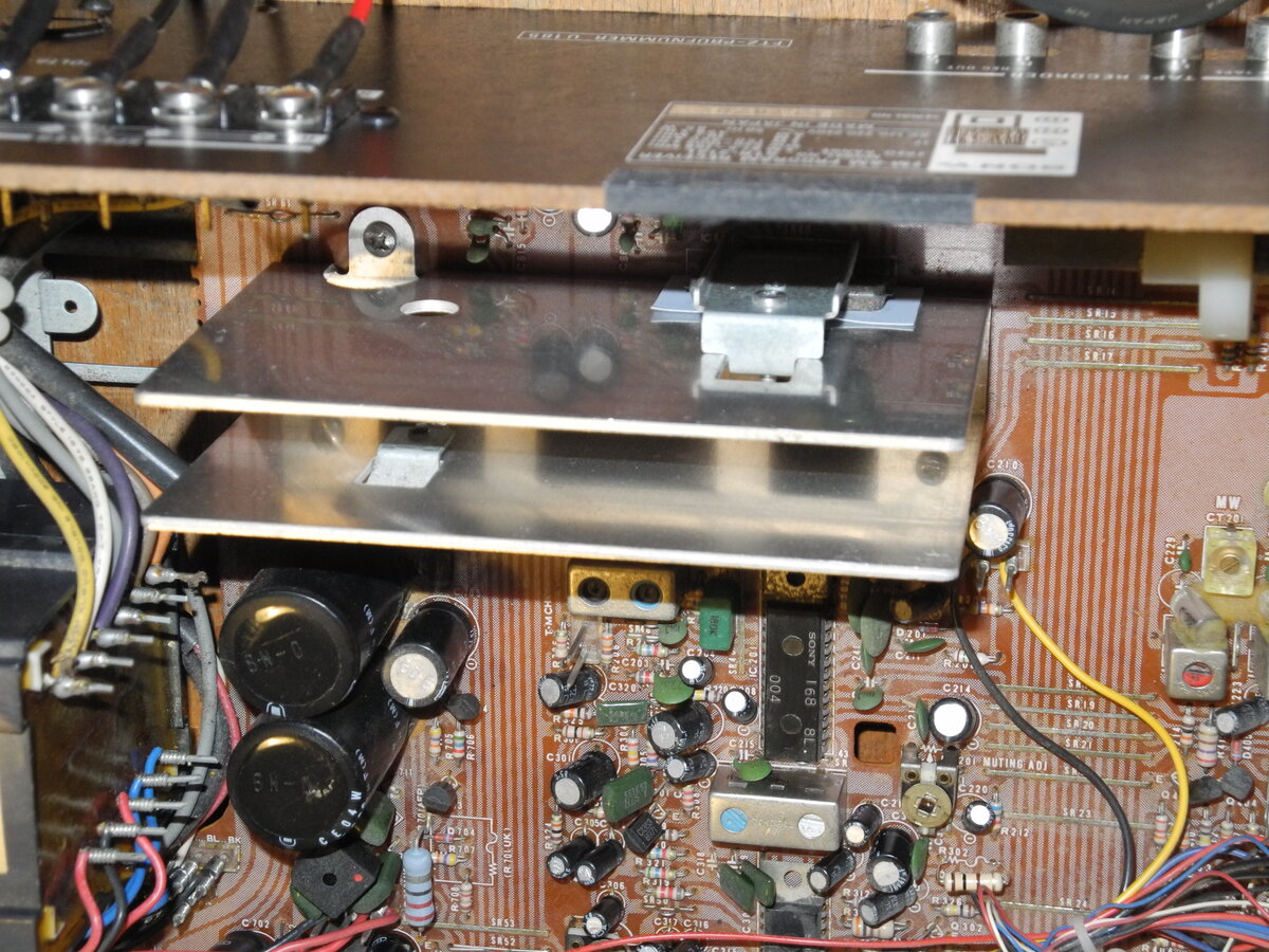
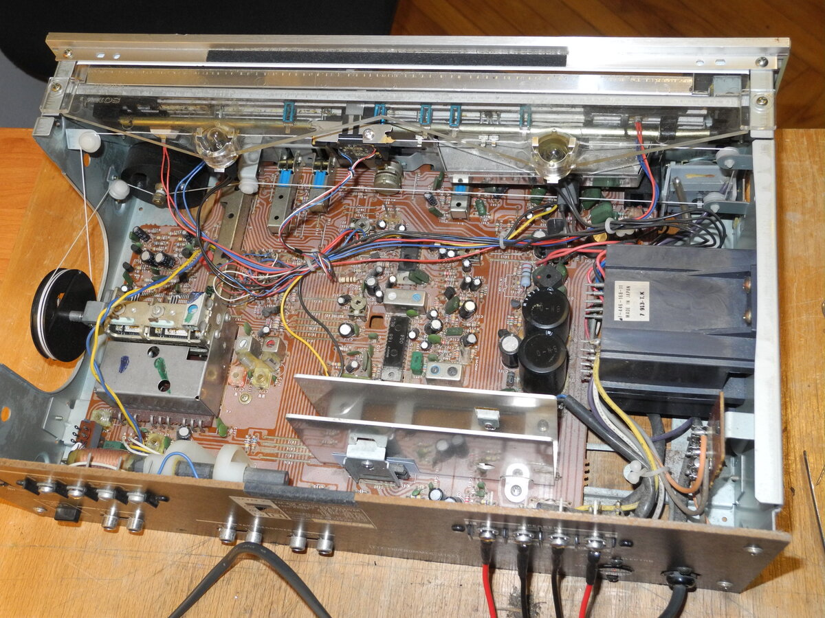
The power amplifier uses two HA1350S ICs for the output stage, with two 3300µF capacitors in the power supply. There is no relay-based speaker protection circuit.
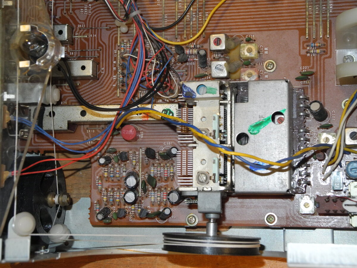
The tuner is built around Sony CX168 and CX178 ICs, while the FM front end features a three-gang tuning capacitor.
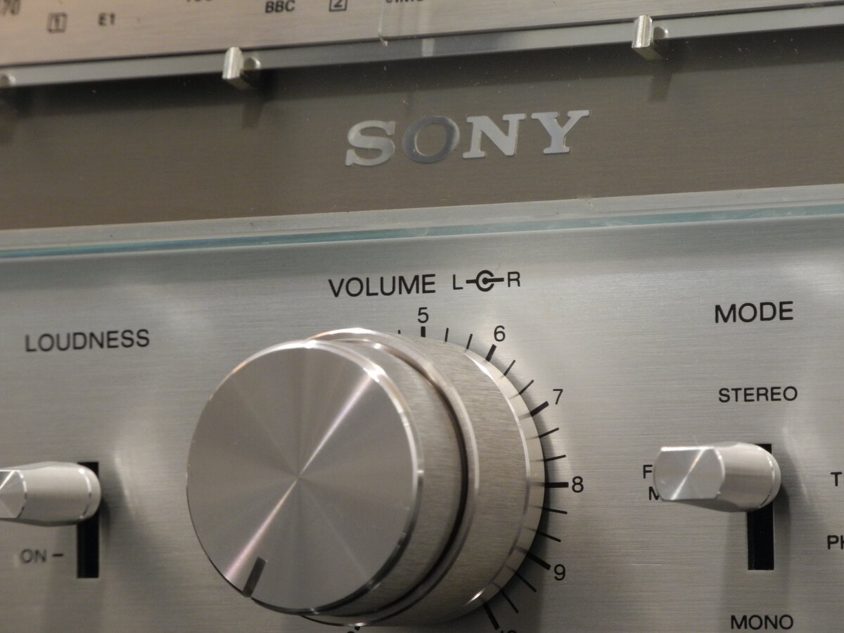
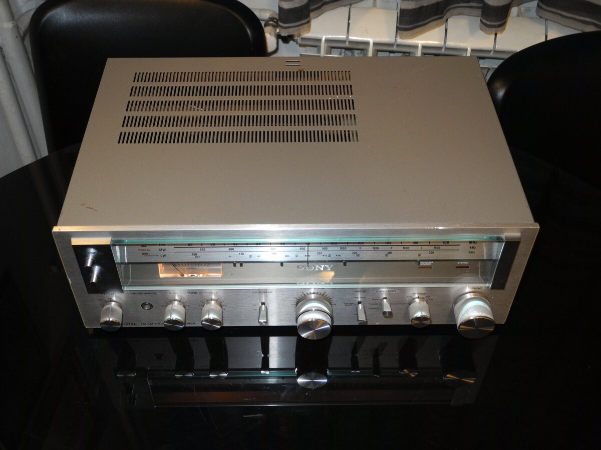
The unit features classic Sony design from that era, with a silver faceplate and stylish, jewelry-like knobs. A notable feature is the set of mechanical markers on the tuning scale, which can be positioned to mark favorite radio stations.
The sound is warm and pleasant, although the receiver is not especially powerful.
Manufacturer: Sony
Status: Active company
Official website: sony.com
General Specifications
Maximum power (8Ω): 15WFrequency response (-3dB): 10Hz-40kHz
THD: 0.7%
Signal to noise ratio (Line): 90dB
Signal to noise ratio (Phono): 70dB
Input sensitivity (Line): 150mV
Input sensitivity (Phono): 2.5mV
Damping factor: 20
Speaker load impedance: 8Ω-16Ω
Dimensions (WHD): 410×145×295mm
Weight: 7.5kg
Produced: 1978-1979
Initial price: 500DM
Measured Values
Maximum power (8Ω): 16WFrequency response (20Hz-20kHz): <1.5dB
Channel imbalance: <0.5dB
THD (1kHz, 1W): 0.012%
THD+N (1kHz, 1W): 0.059%
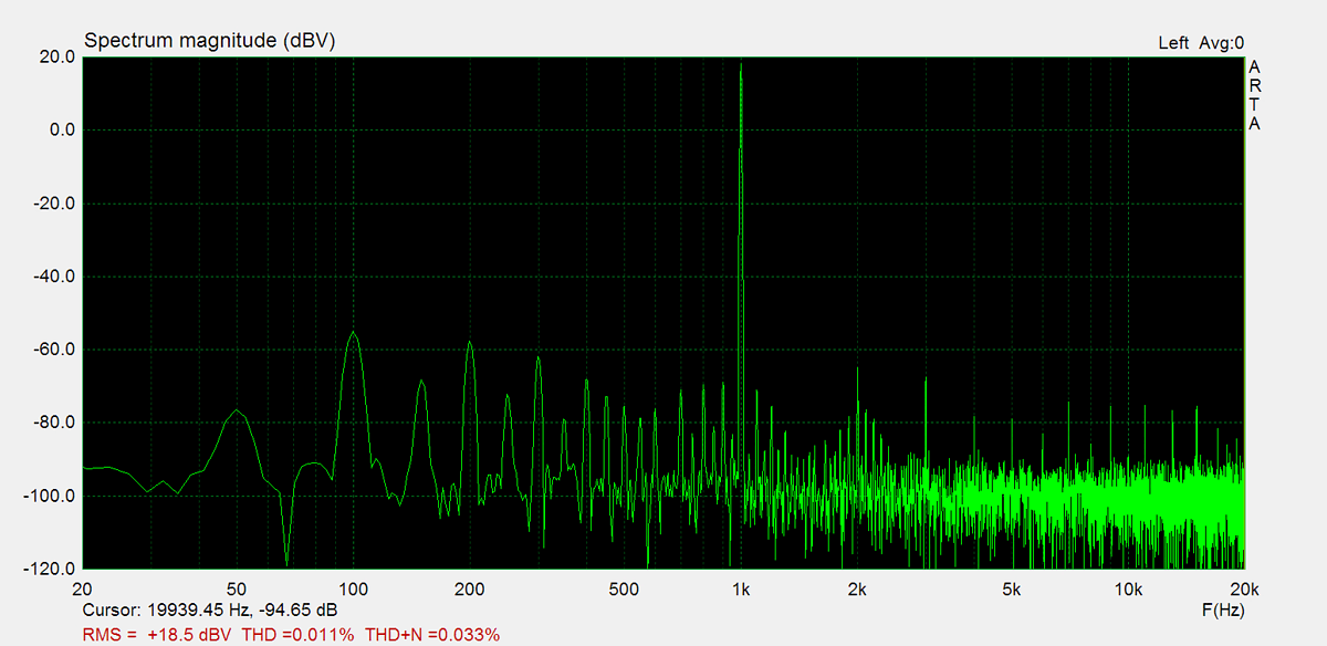
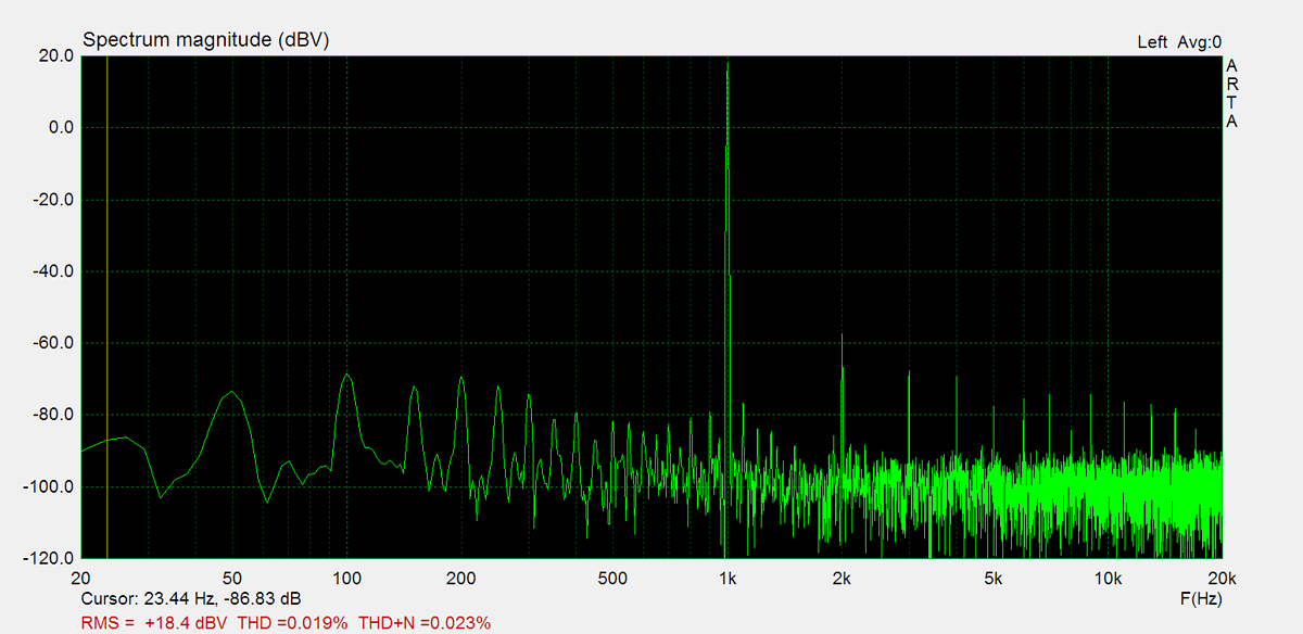
THD (1kHz, 10W): 0.019%
THD+N (1kHz, 10W): 0.033%
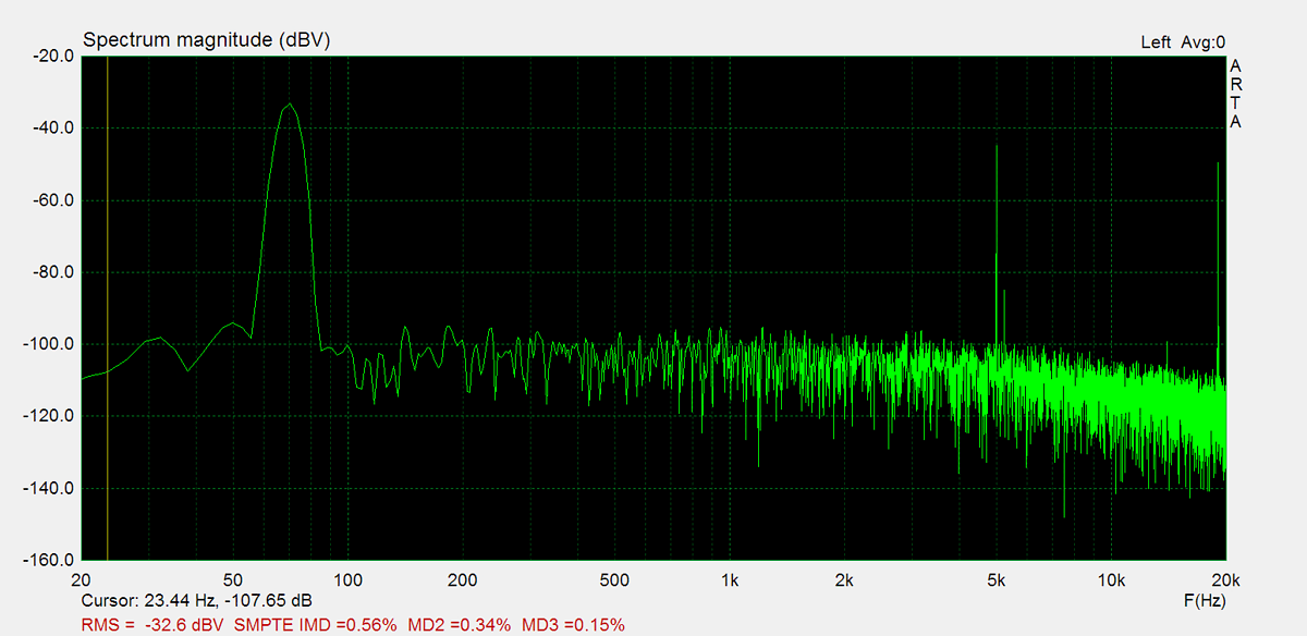
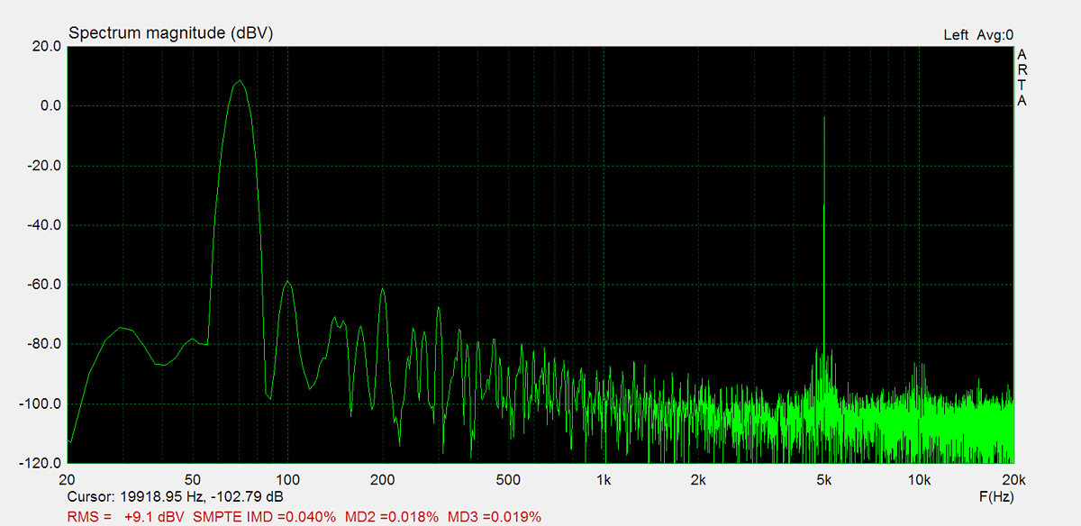
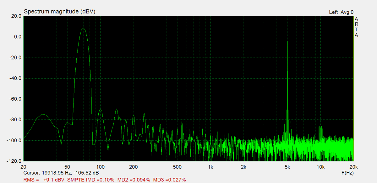
IMD (70Hz, 5kHz, 1W): 0.1%
Noise: -56.9dB
Amplification: 83.2
DC offset L: -2.3mV
DC offset R: 0.3mV
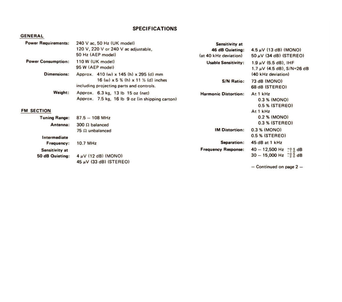
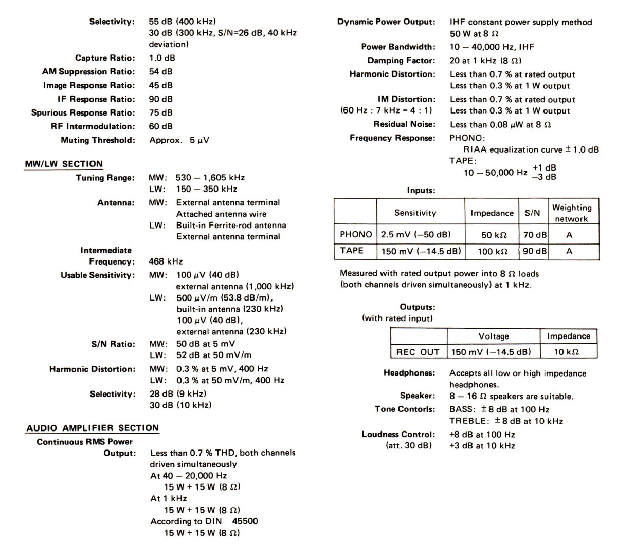
Factory Specification Sheet
Factory specification images are sourced directly from the device's original service manual or user manual. These documents are produced by the manufacturer and provide authoritative information on the product's specifications.
Maximum Power
Maximum power is measured using 8Ω resistors on both channels. A 1kHz sine wave input signal is applied and gradually increased until higher harmonics rise significantly. Typically, this is the point at which output clipping occurs.
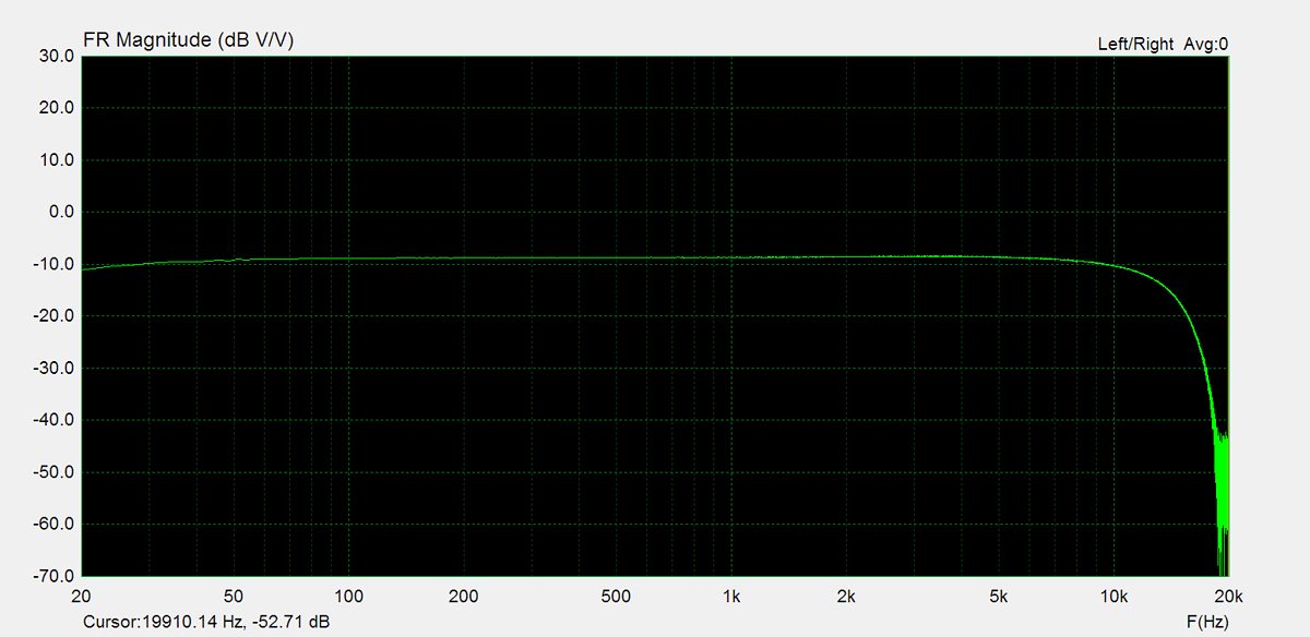
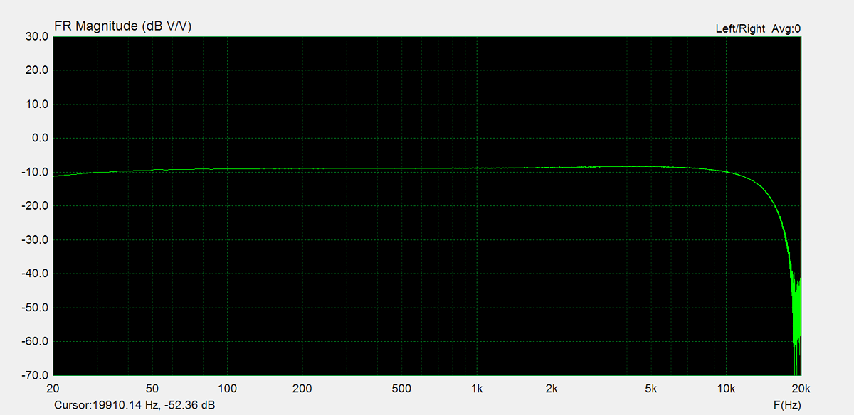
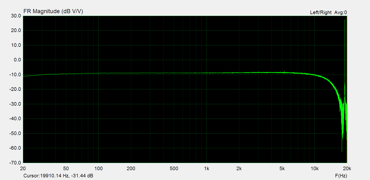
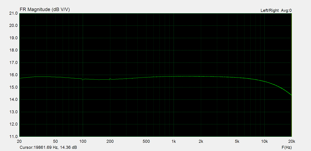
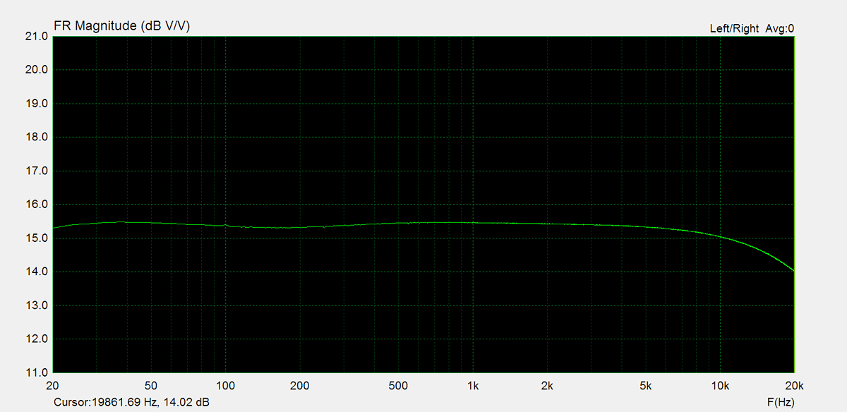
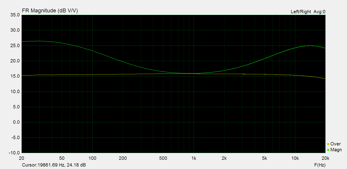
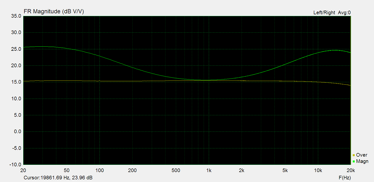
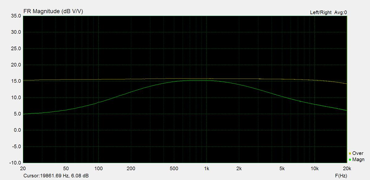
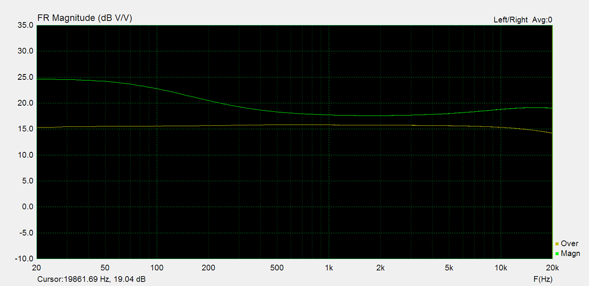
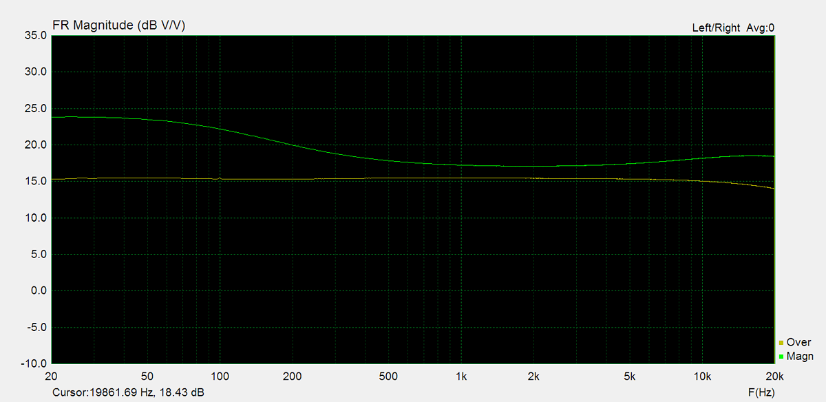
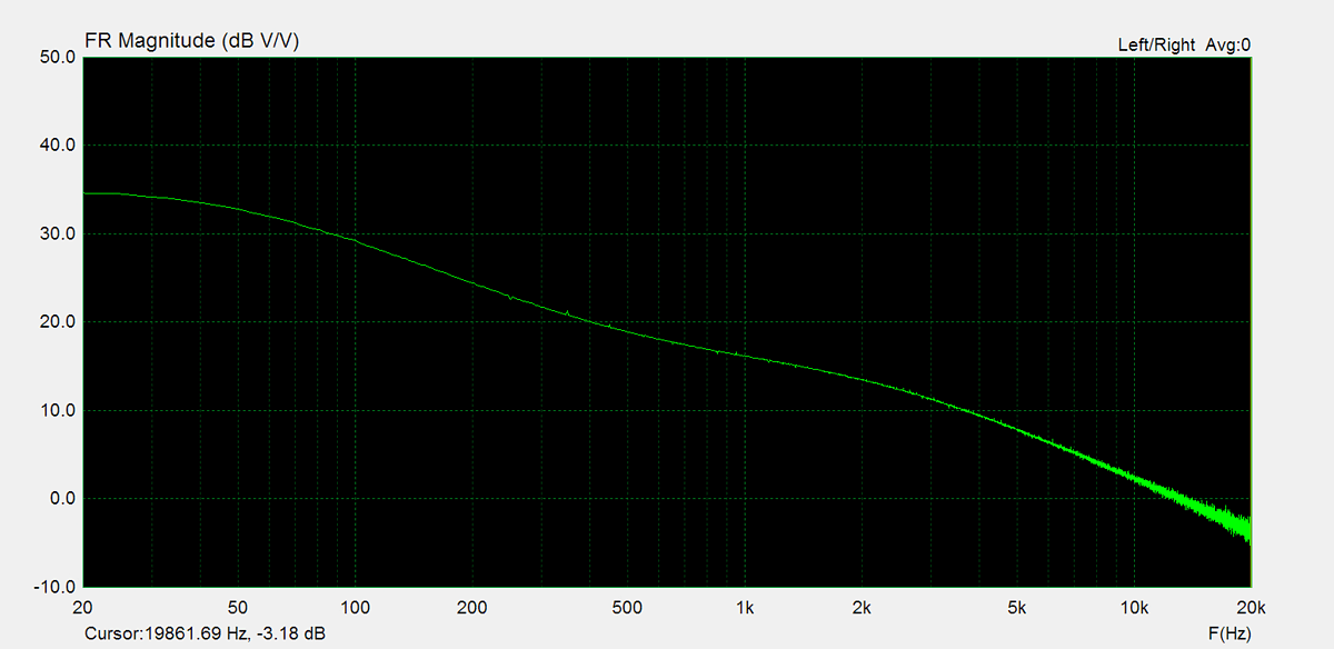
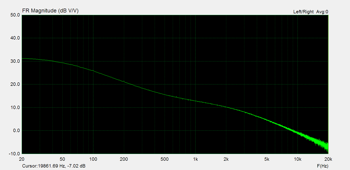
Frequency Response
Frequency response is measured using several equilizer settings. 'Flat' indicates the tone controls are either turned off or set to their neutral position. 'Max' and 'Min' refer to the maximum and minimum tone control positions, respectively. In the phono section, the expected response follows the RIAA equalization curve.

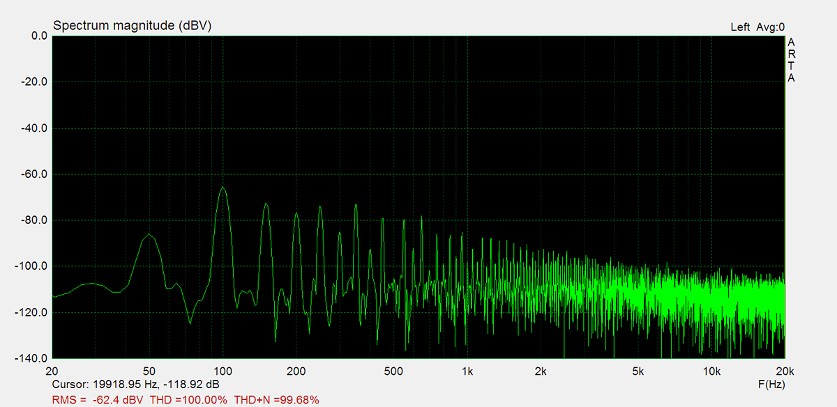
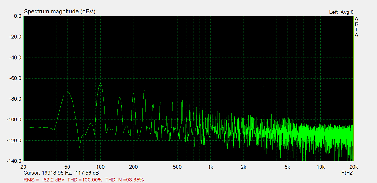
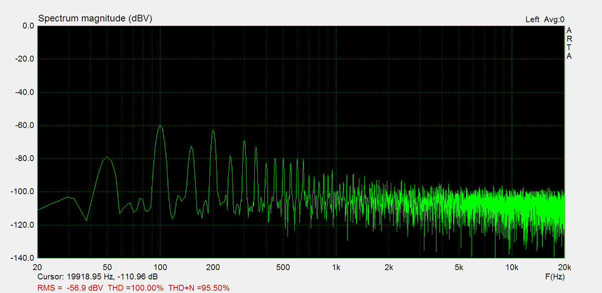
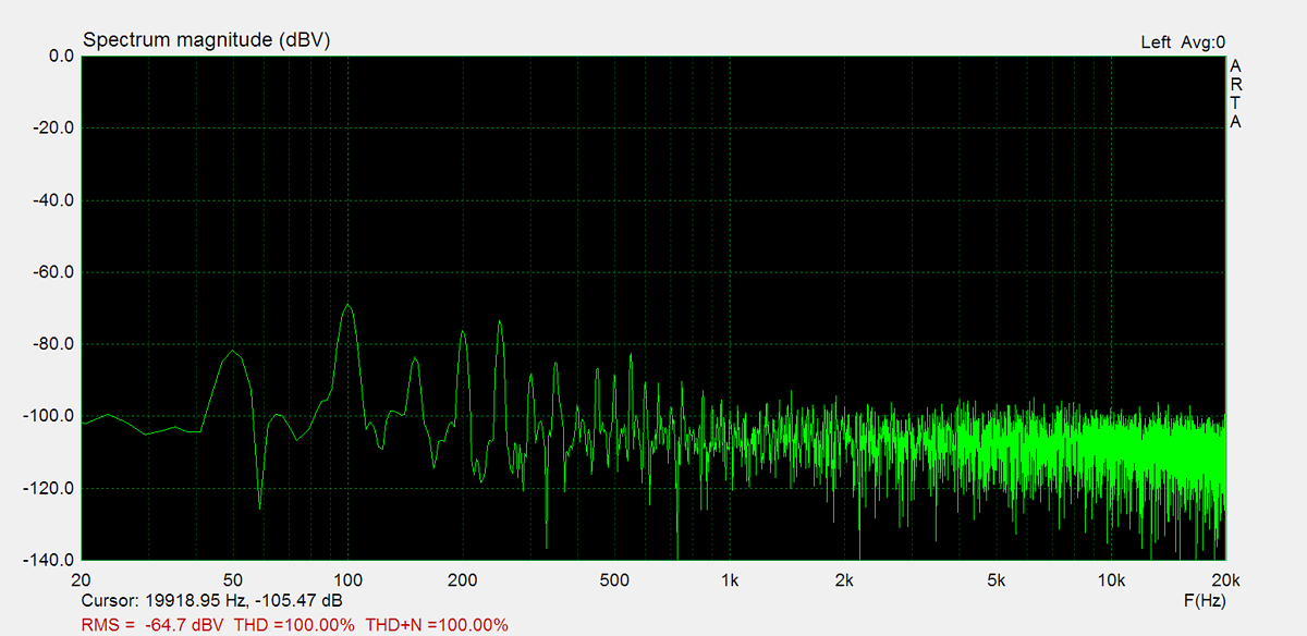
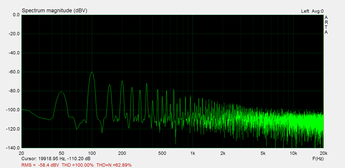
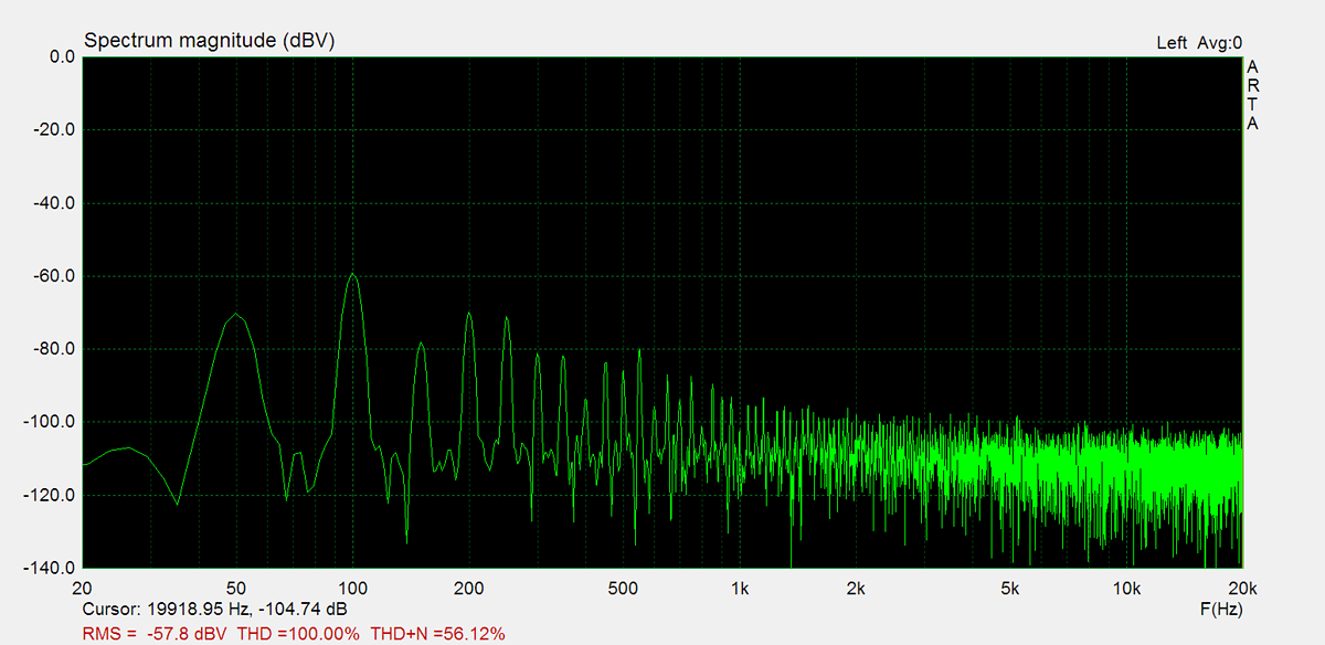
Residual Noise
These graphs display the noise levels at various volume positions. To eliminate any interference from the input signal, the input lines are shorted during the measurement. Generally, the noise is highest at the mid-point of the volume range (50%)
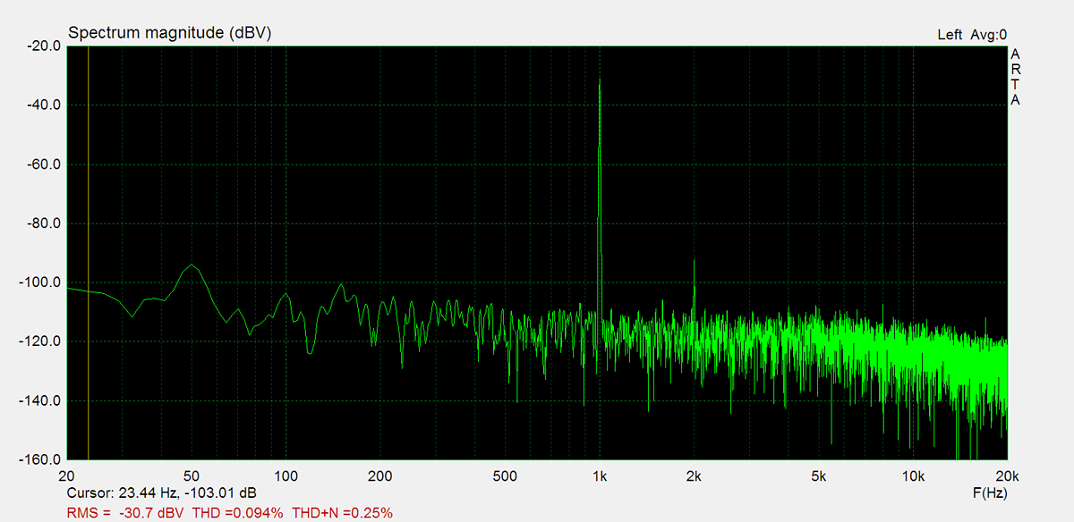
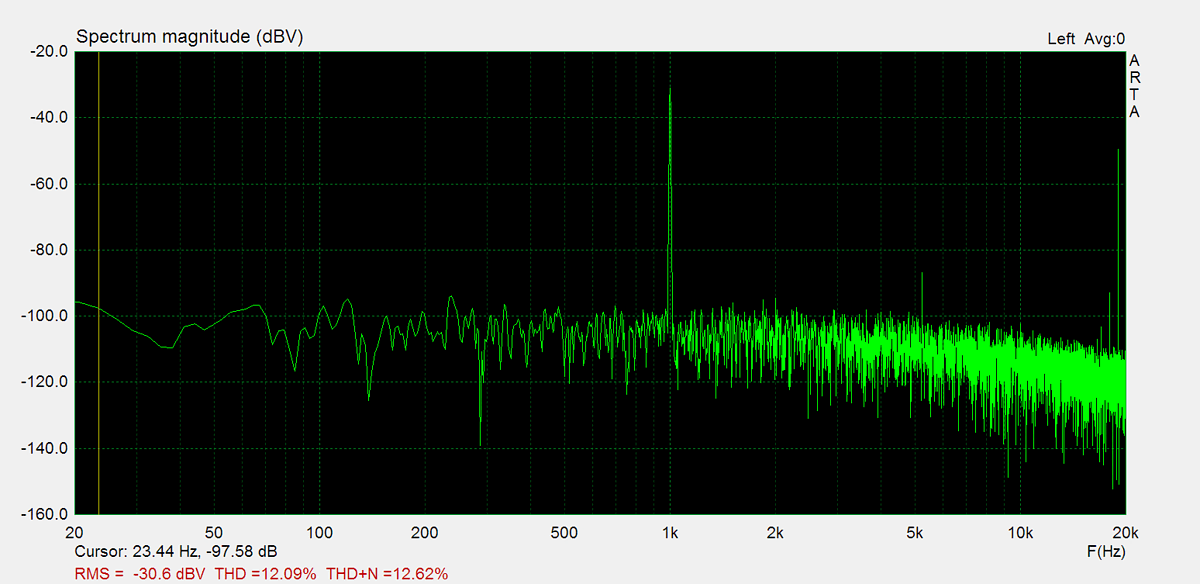
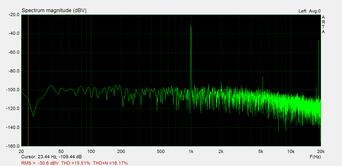
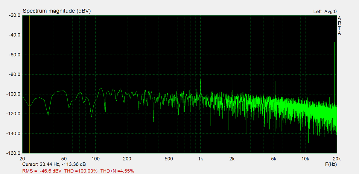
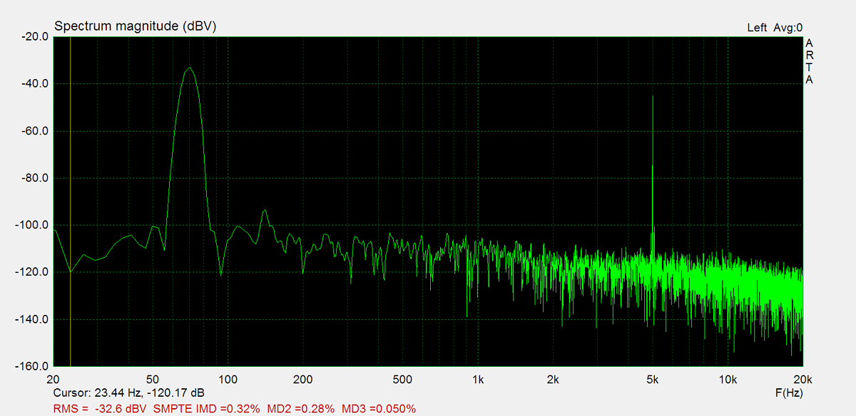
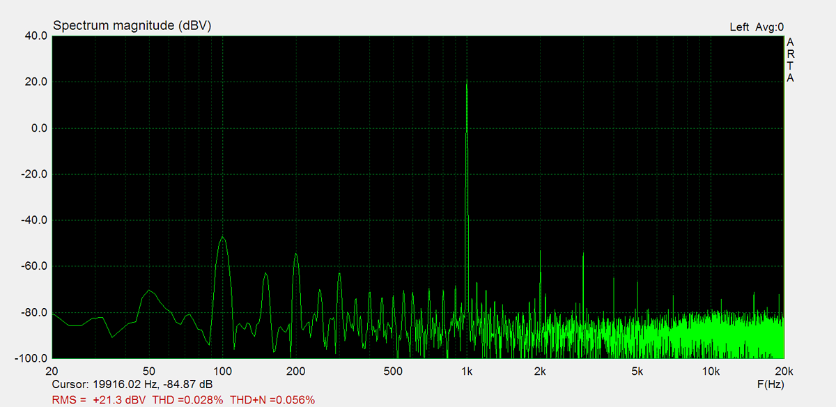
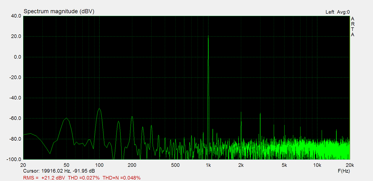
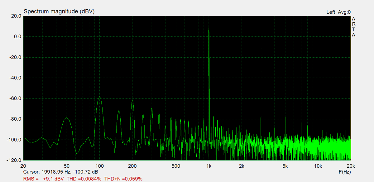
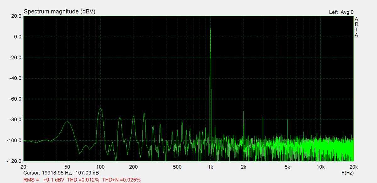
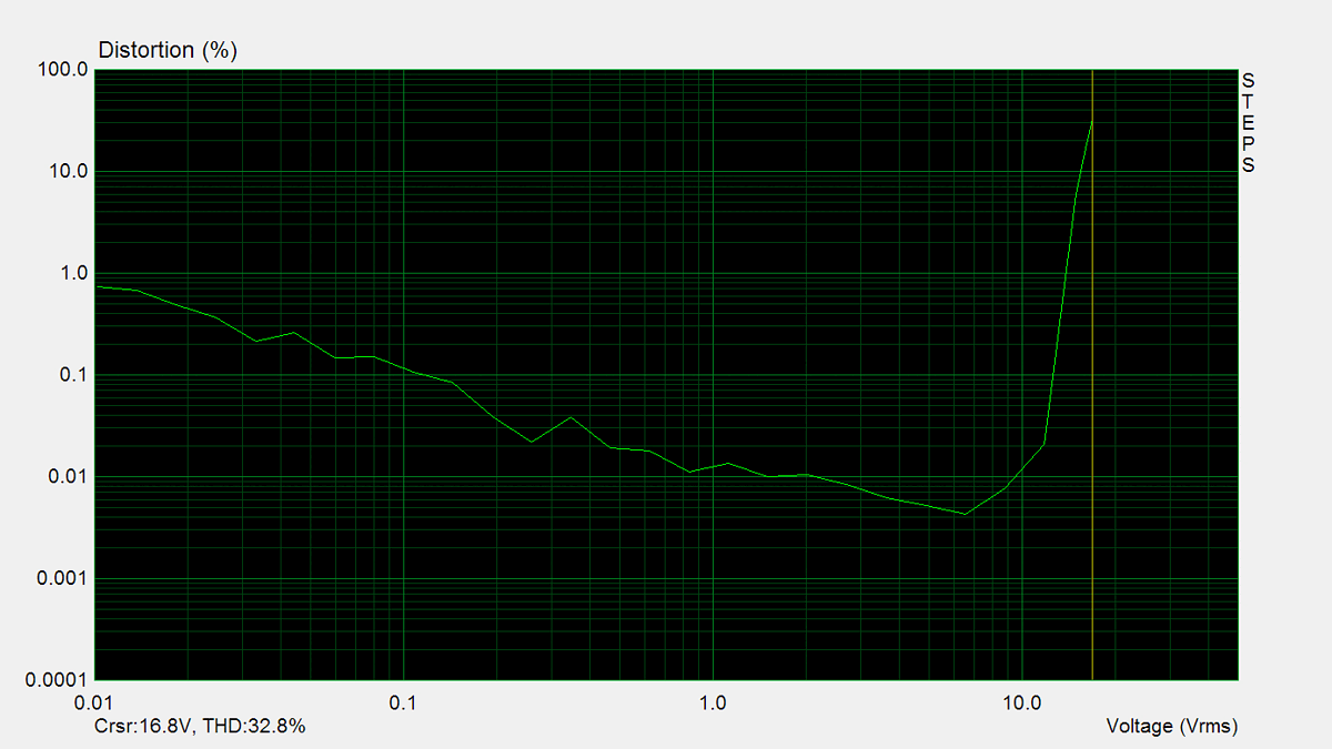
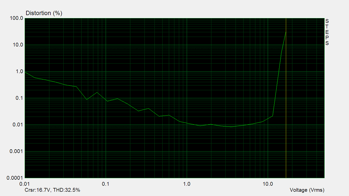
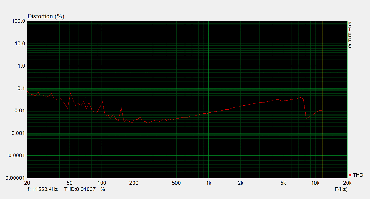
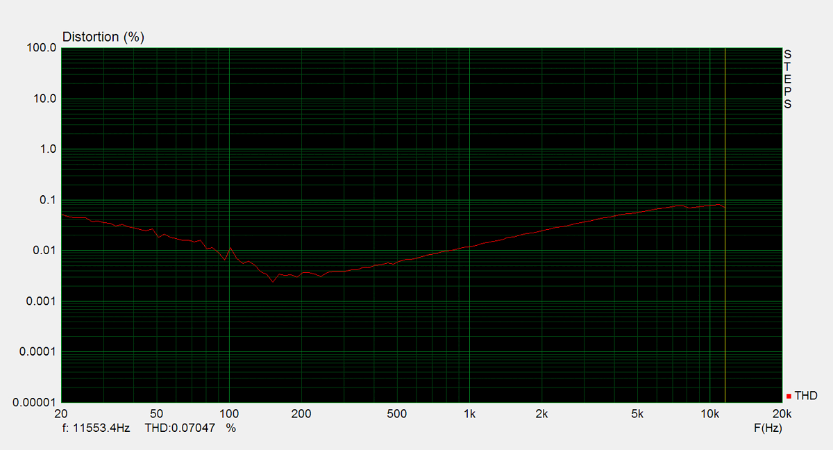
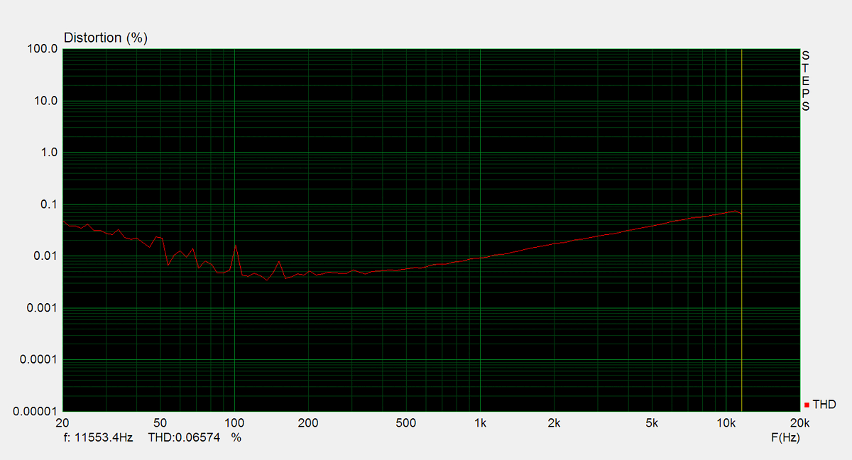
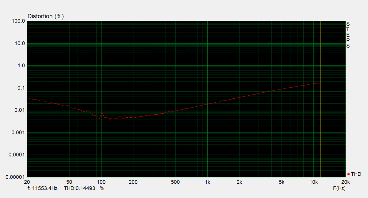
Distorsion
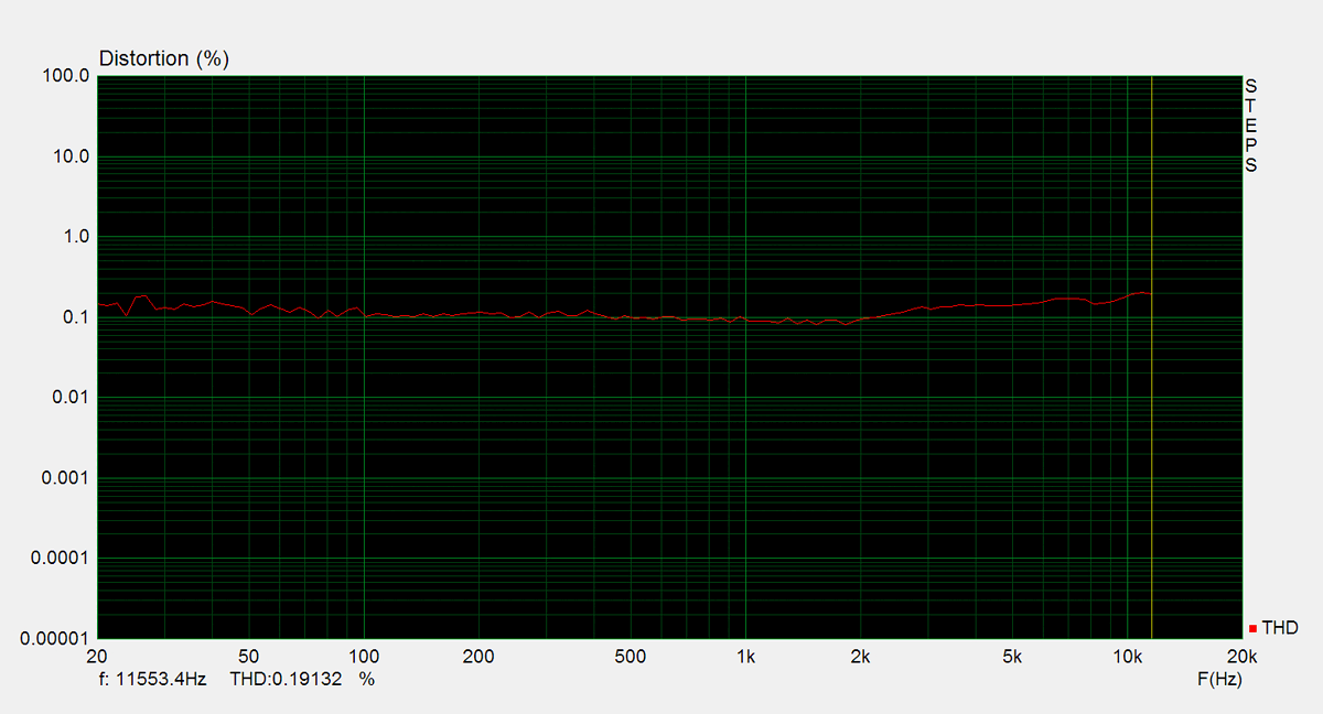
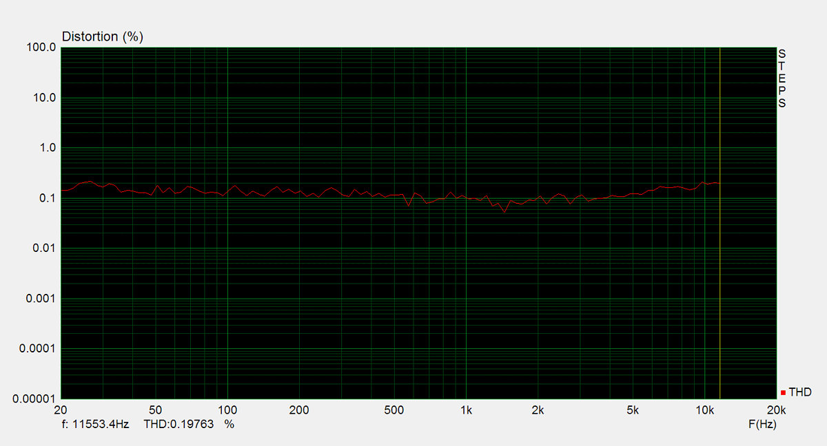
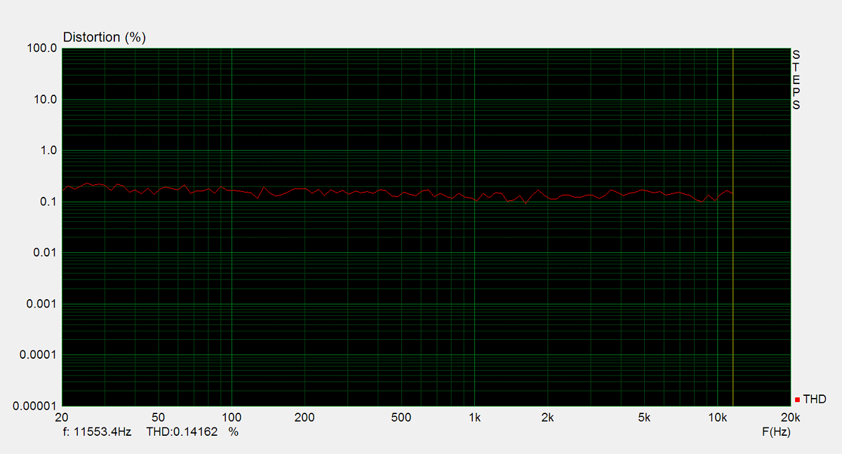
Total harmonic distortion (THD) is measured using a 1kHz sine wave input, with the output level adjusted to meet different conditions. Intermodulation distortion (IMD) is measured using 'two sine' input signal. THD versus voltage is measured with a 1kHz sine wave input, while THD versus frequency is measured at various output levels.
FM Tuner
Measurements of the tuner section were performed using an FM signal generator, with its output fed directly into the antenna input. AM measurements were not conducted.