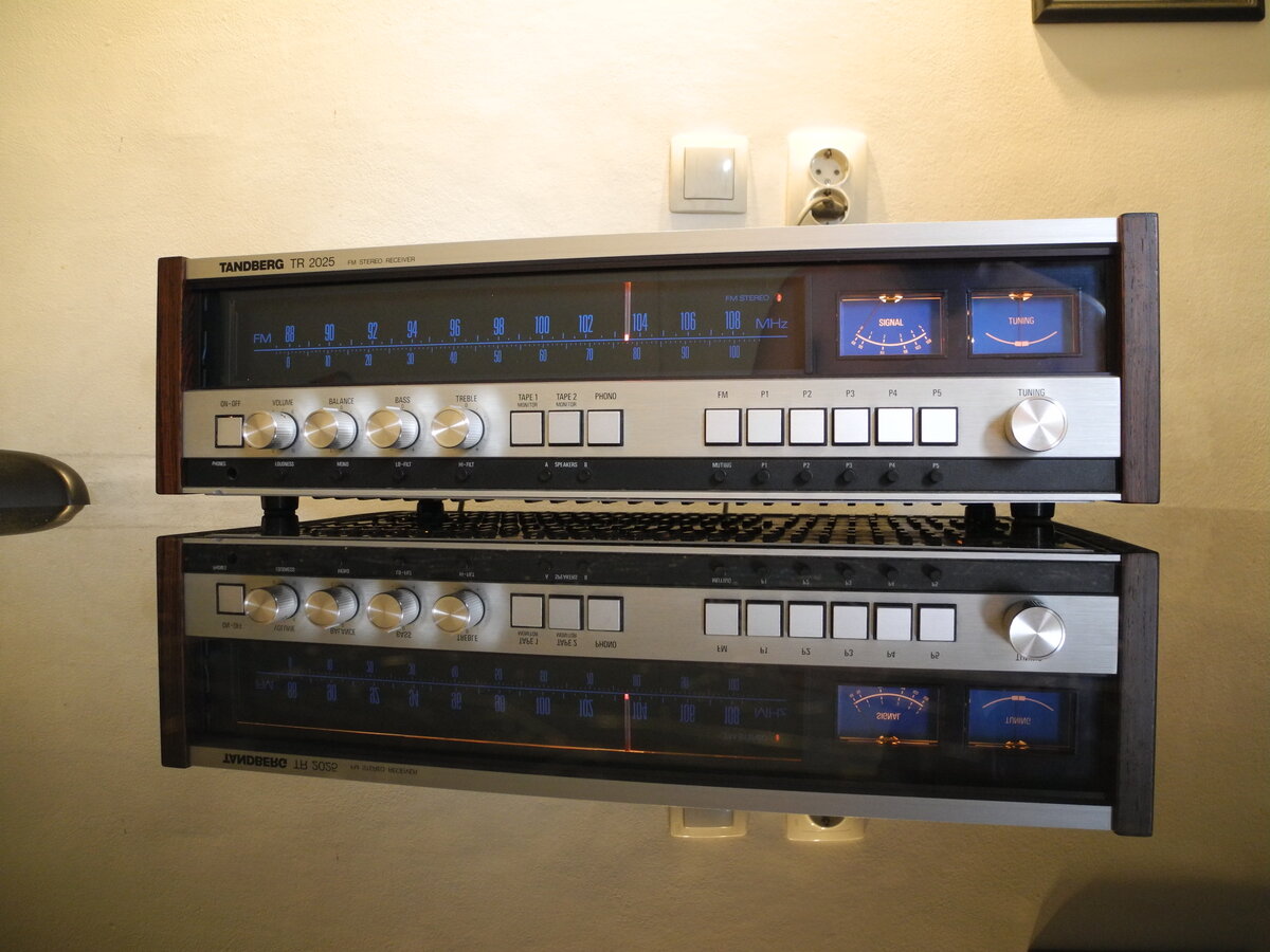
Tandberg TR 2025
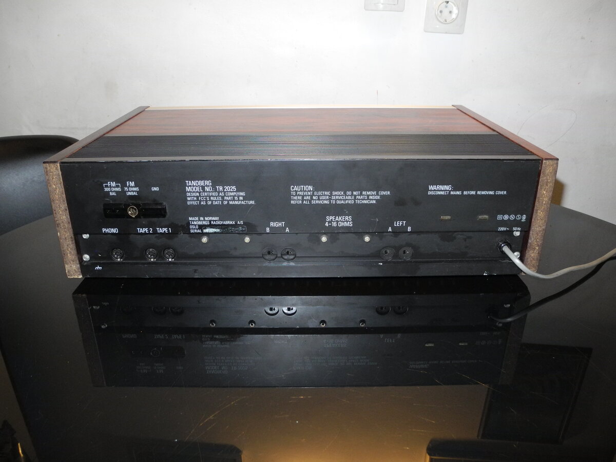
The Tandberg TR 2025 is a stereo receiver from the mid-1970s, capable of delivering up to 25 watts per channel into 8Ω speakers. As the smallest model in the Tandberg TR 20xx series, it combines clean Scandinavian design with excellent FM tuner performance.
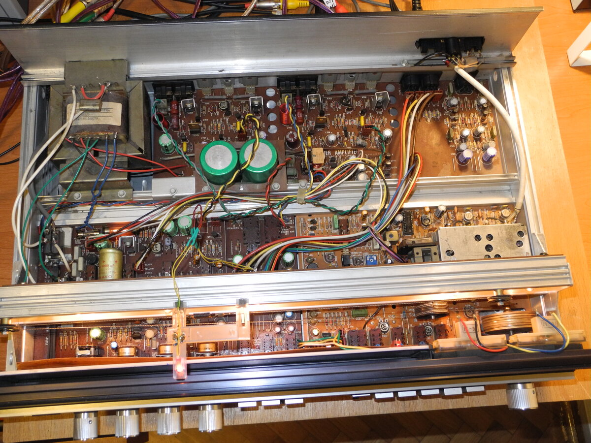
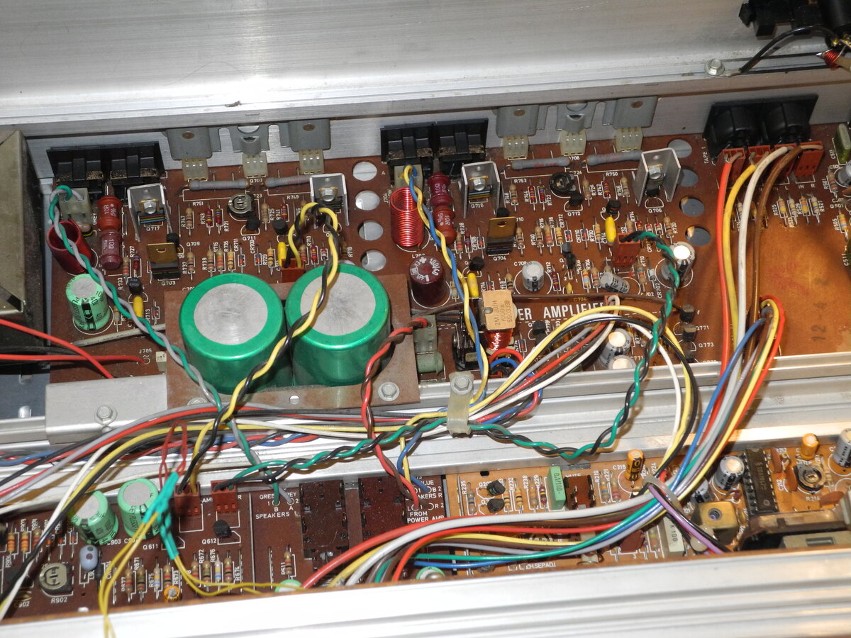
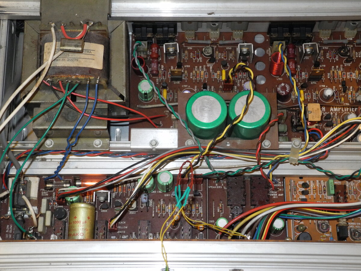
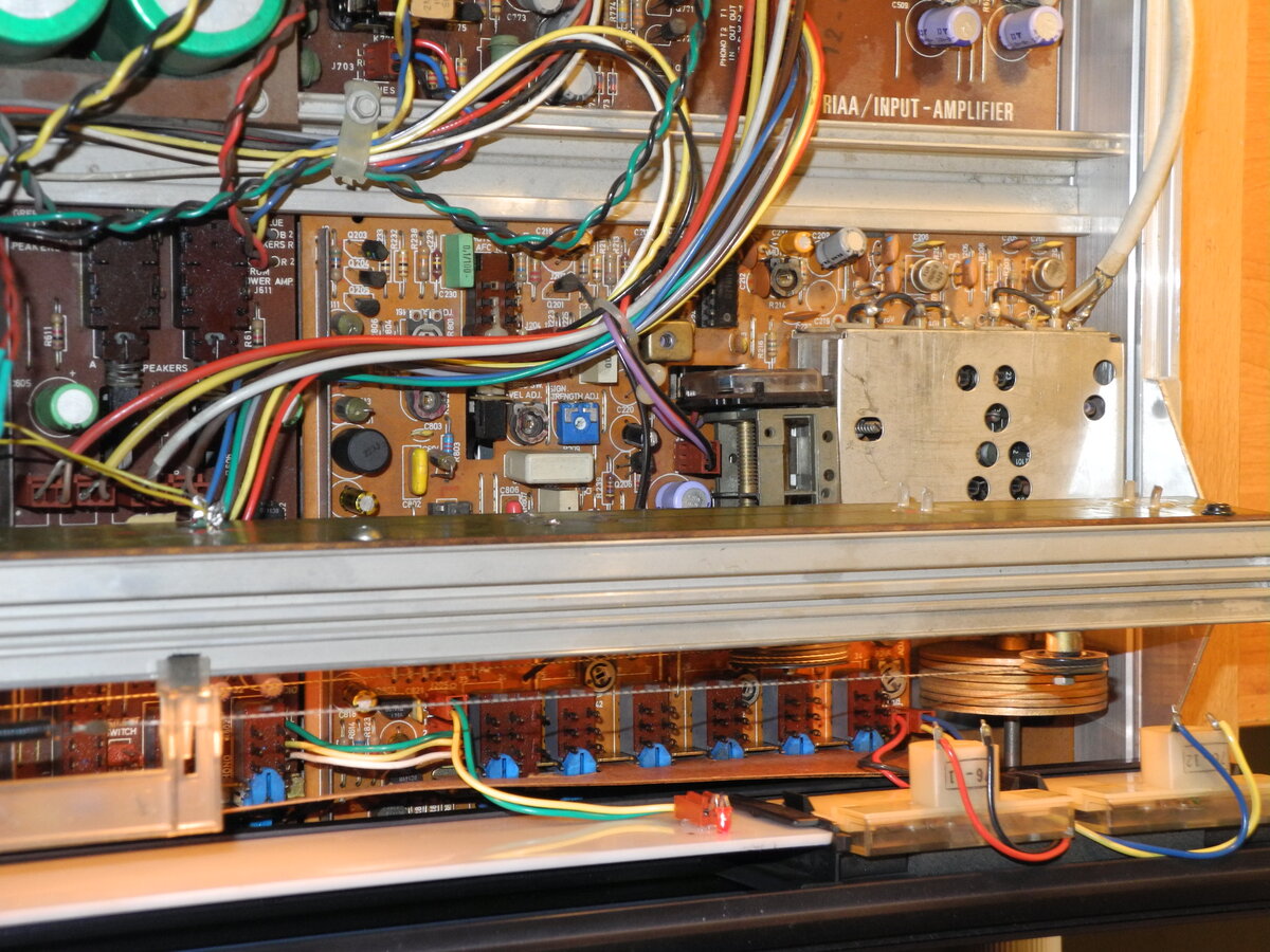
The power amplifier uses complementary BD609 and BD610 output transistors and includes a speaker protection relay. Power supply filtering is handled by two 4700µF capacitors, providing stable operation at rated power.
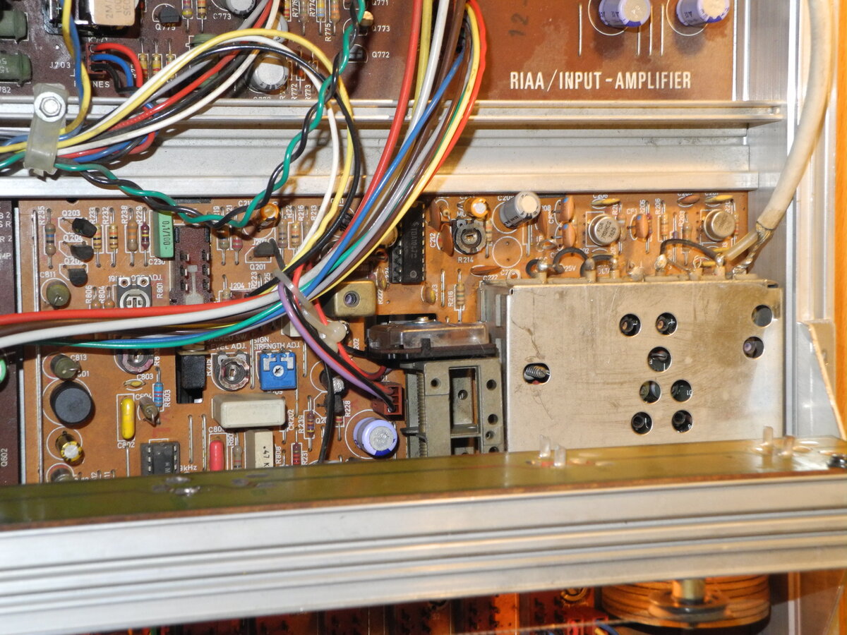
The TR 2025 is equipped with an FM-only tuner and offers 5 tuning preset stations, a feature not found on larger models in the series. The tuner front end uses 4 varicap diodes, while FM demodulation is performed by the TDA1047 IC. Stereo decoding is handled by either the TCA4500 or MC1310 IC, depending on the production series.
Combining solid build quality with warm and detailed sound, the TR 2025 is a fine example of Tandberg's precision engineering and understated elegance.
Manufacturer: Tandberg
Status: Defunct company
Source: Wikipedia (Tandberg)

General Specifications
Maximum power (8Ω): 25WFrequency response (-1.5dB): 8Hz-50kHz
THD: 0.15%
IMD: 0.15%
Channel separation: 60dB
Signal to noise ratio (Line): 61dB
Signal to noise ratio (Phono): 60dB
Input sensitivity (Line): 170mV
Input sensitivity (Phono): 2.3mV
Damping factor: 50
Speaker load impedance: 4Ω-16Ω
Dimensions (WHD): 515×143×340mm
Weight: 8.3kg
Produced: 1976-1977
Initial price: 1200DM
Measured Values
Maximum power (8Ω): 28WFrequency response (20Hz-20kHz): <1.0dB
Channel imbalance: <1.0dB
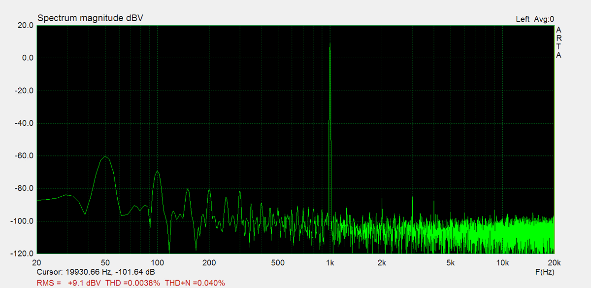
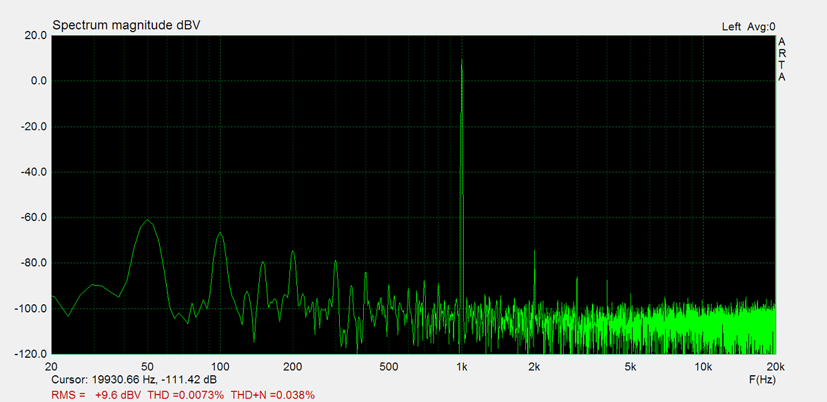
THD (1kHz, 1W): 0.073%
THD+N (1kHz, 1W): 0.04%
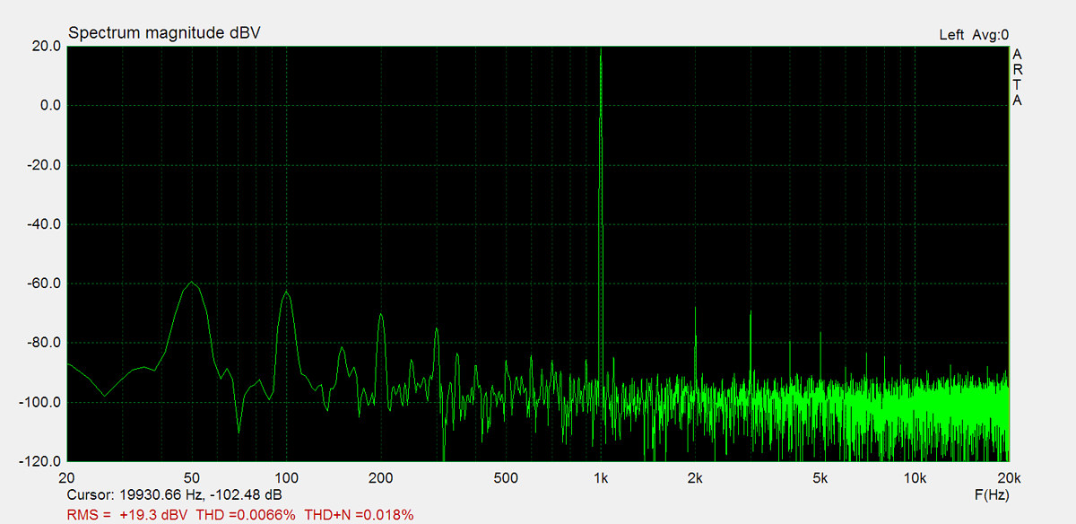
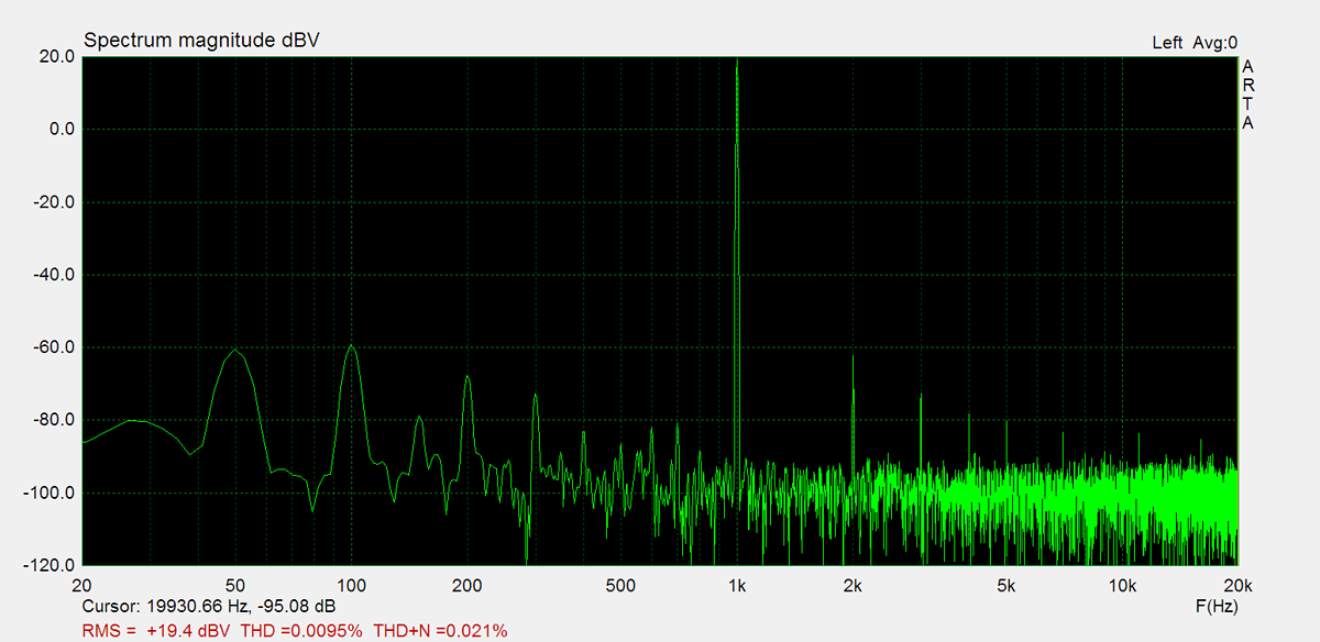
THD (1kHz, 10W): 0.0095%
THD+N (1kHz, 10W): 0.021%
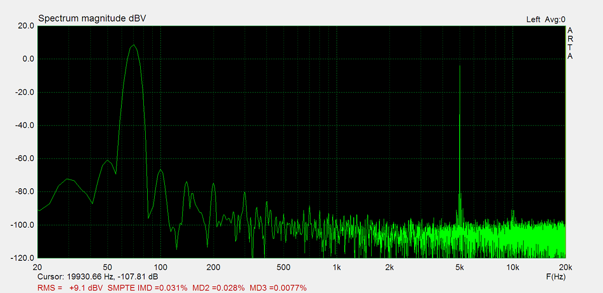
IMD (70Hz, 5kHz, 1W): 0.031%
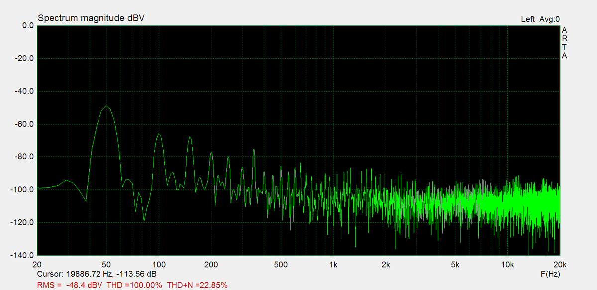
Noise: -48.4dB
Amplification: 89.4
DC offset L: 9.2mV
DC offset R: 2.3mV
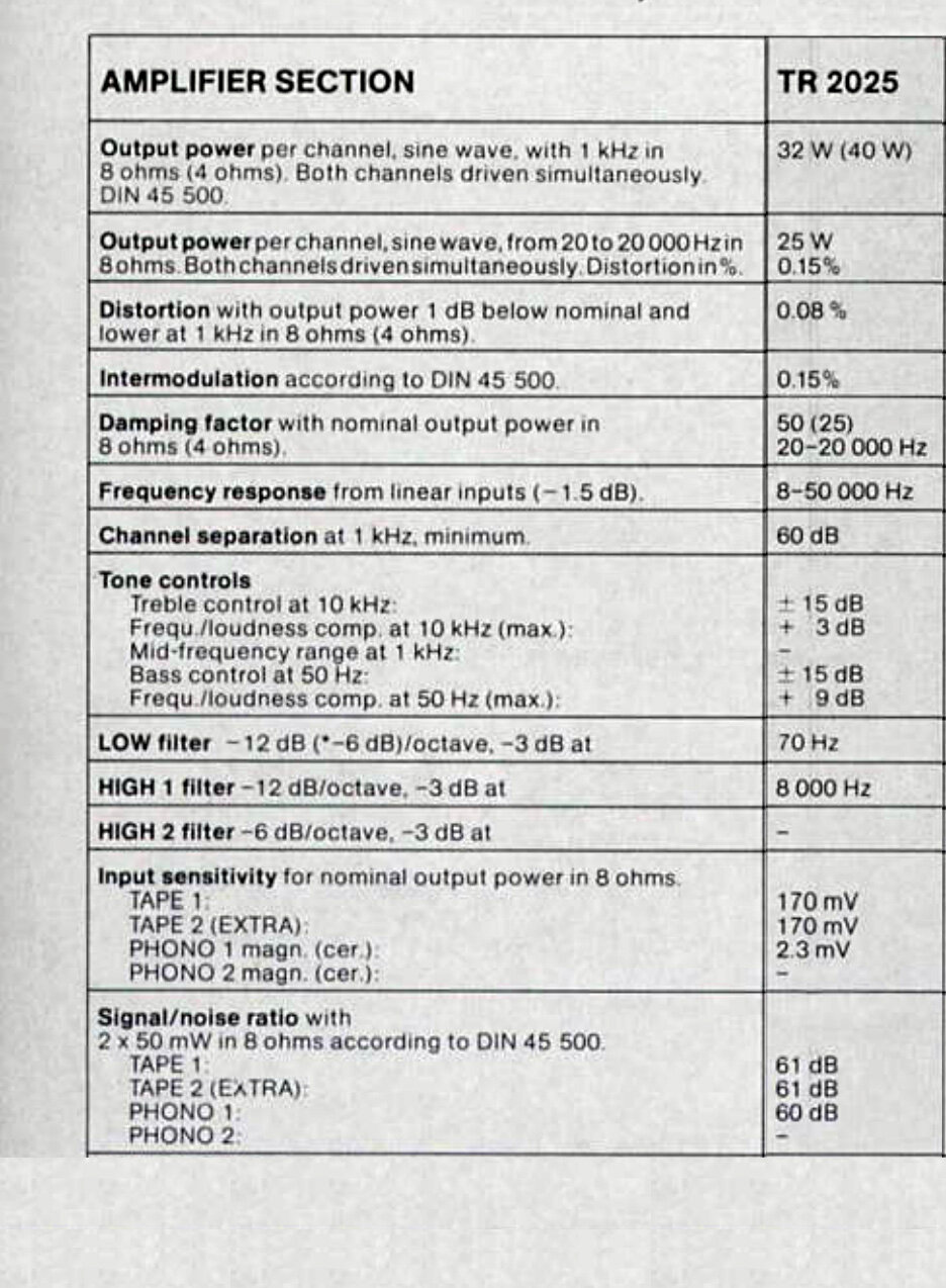
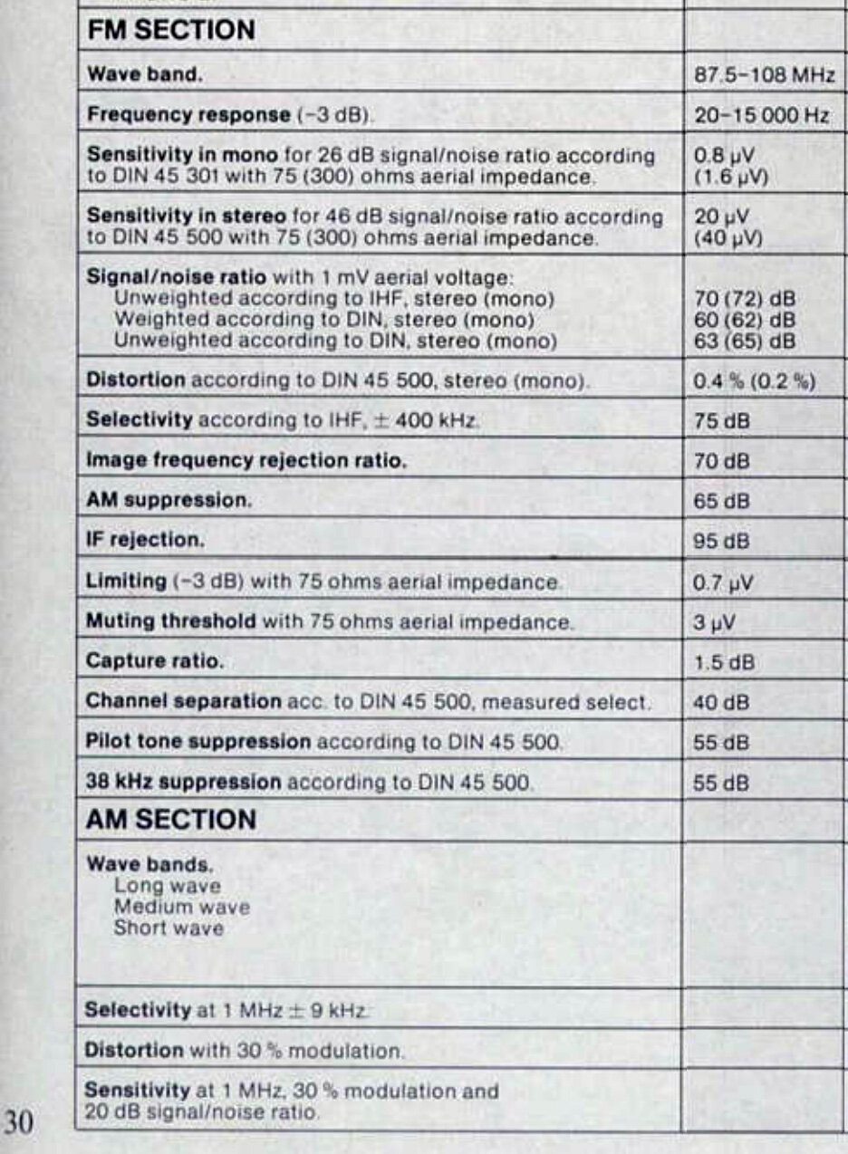
Factory Specification Sheet
Factory specification images are sourced directly from the device's original service manual or user manual. These documents are produced by the manufacturer and provide authoritative information on the product's specifications.
Maximum Power
Maximum power is measured using 8Ω resistors on both channels. A 1kHz sine wave input signal is applied and gradually increased until higher harmonics rise significantly. Typically, this is the point at which output clipping occurs.

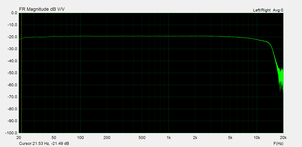
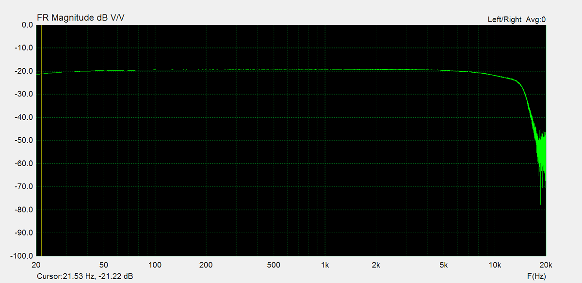
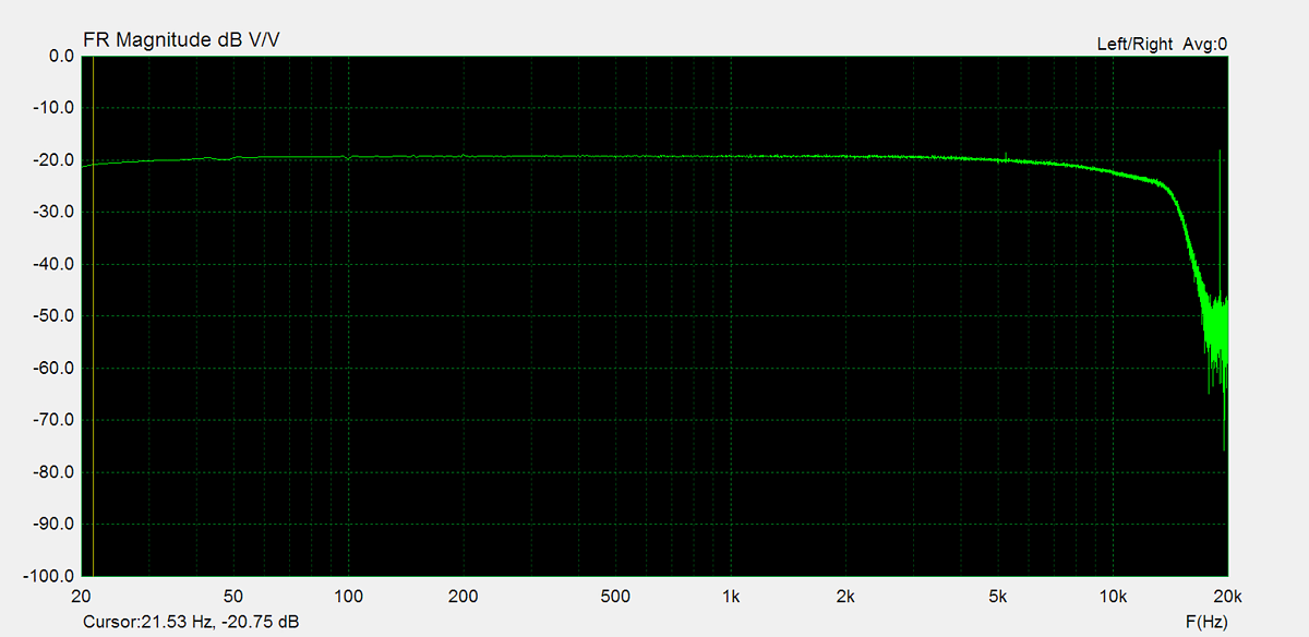
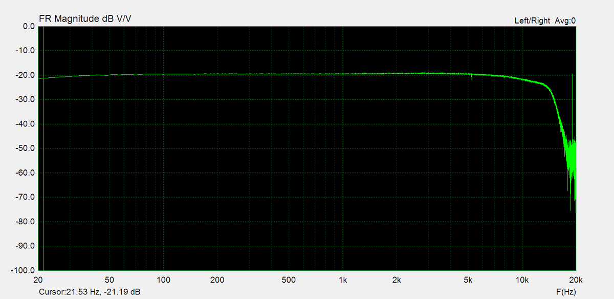
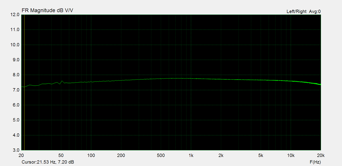
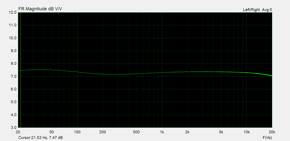
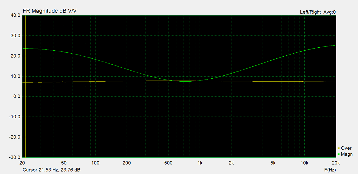
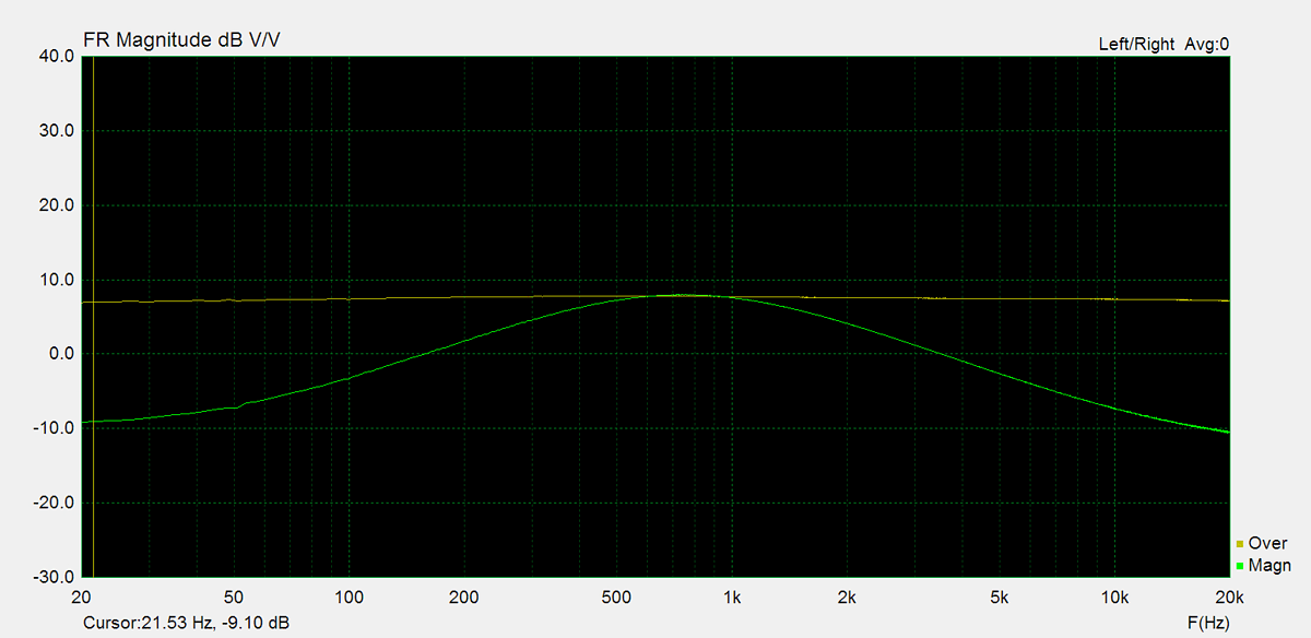
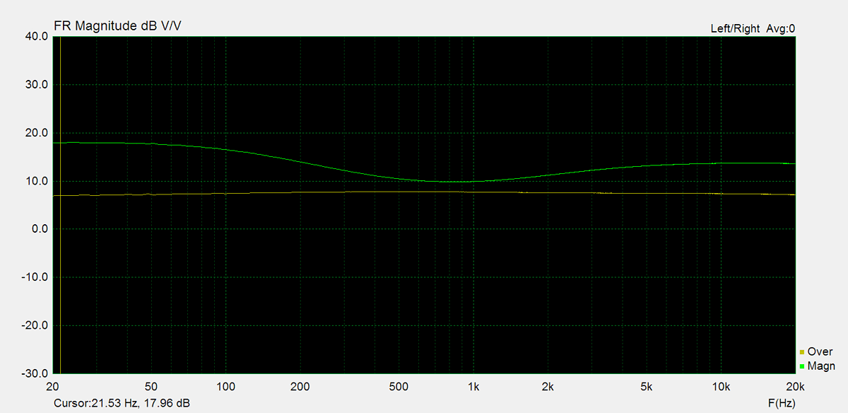
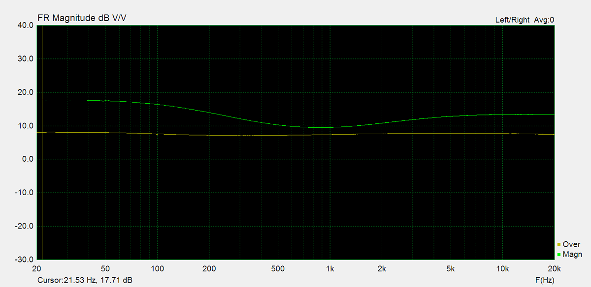
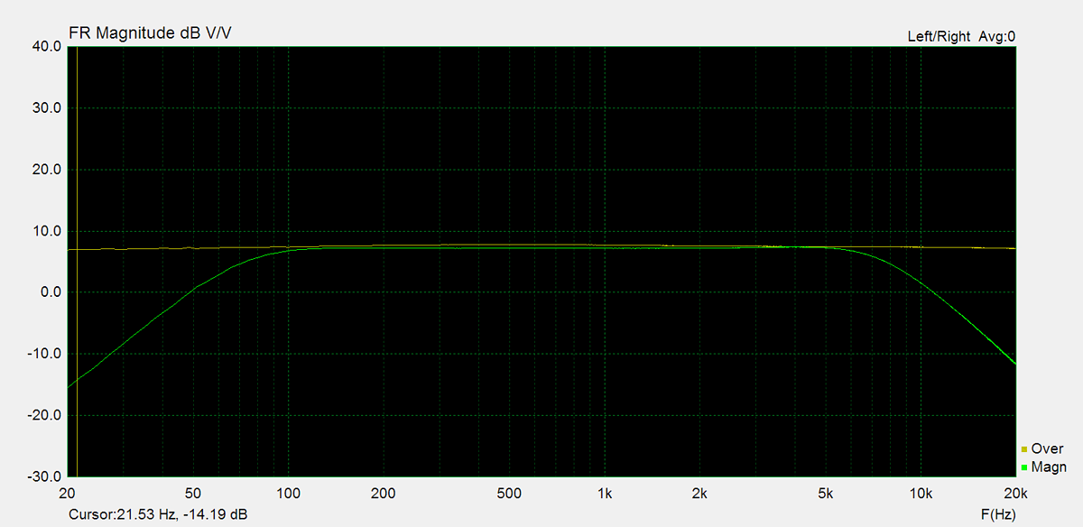
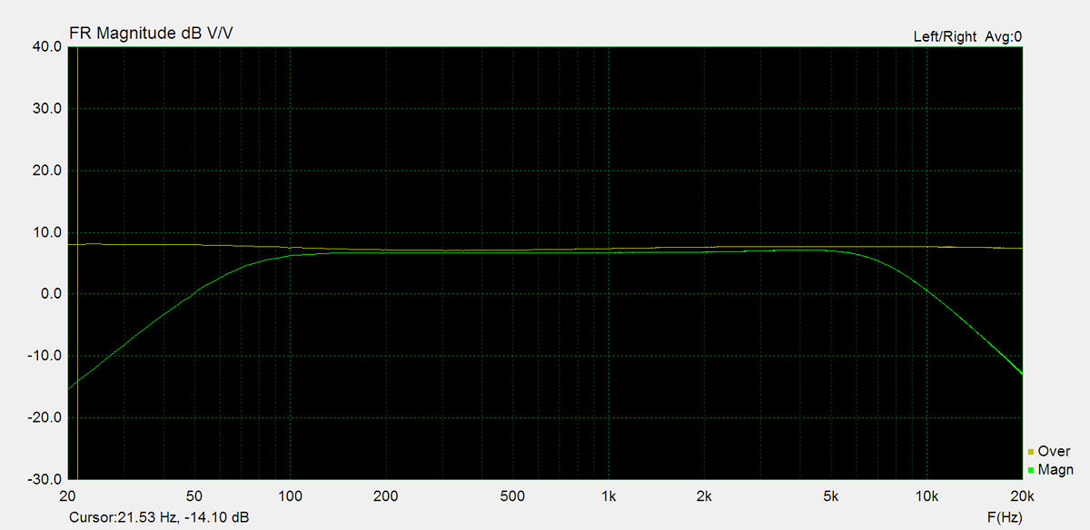
Frequency Response
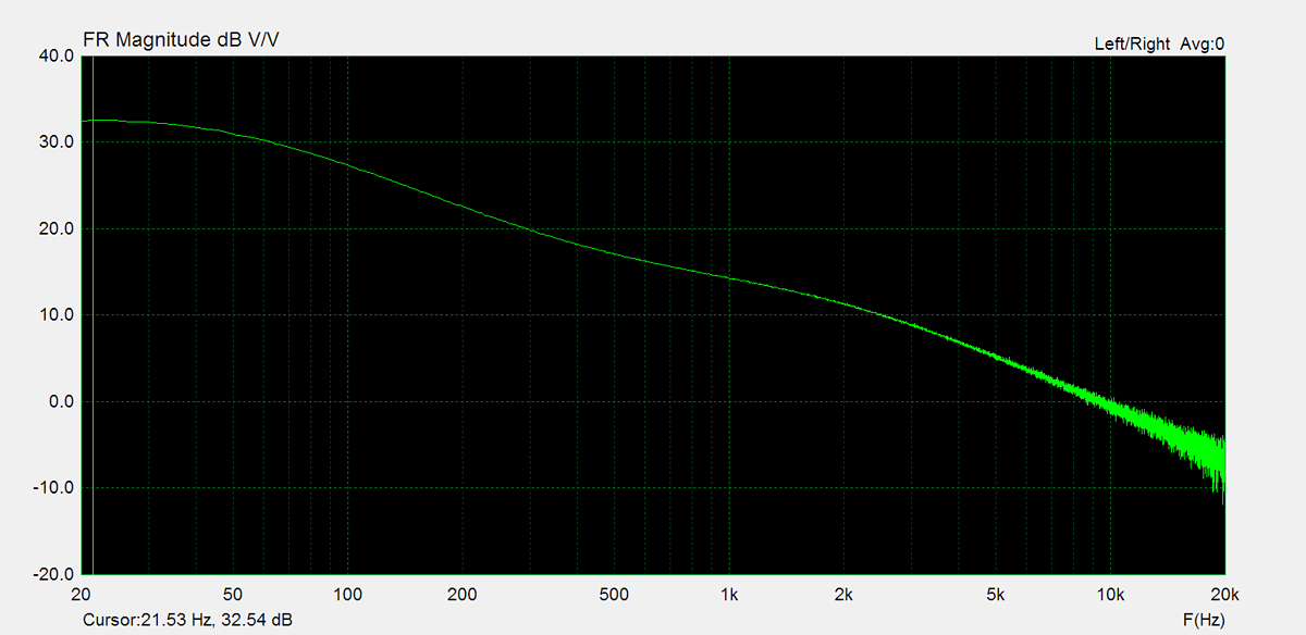
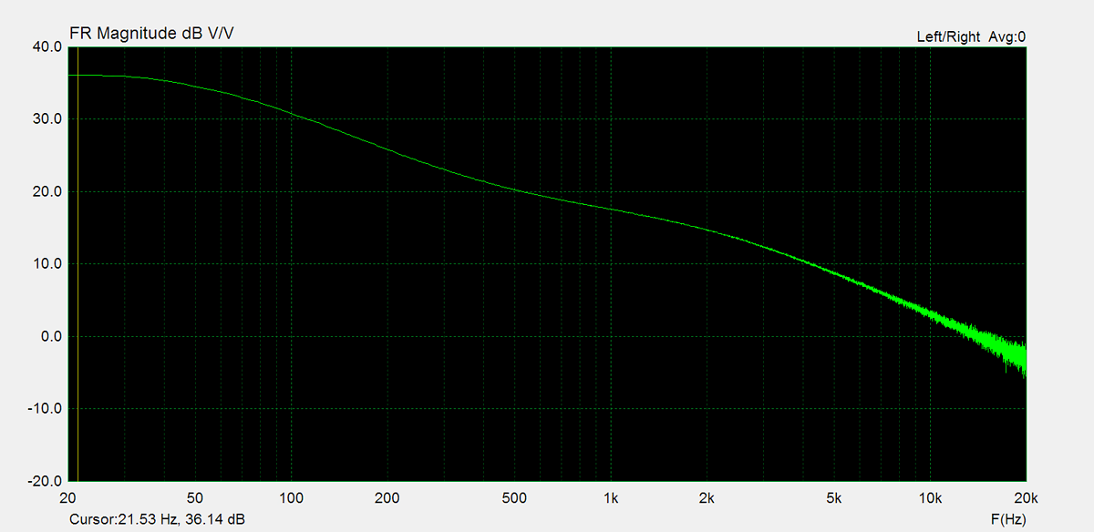
Frequency response is measured using several equilizer settings. 'Flat' indicates the tone controls are either turned off or set to their neutral position. 'Max' and 'Min' refer to the maximum and minimum tone control positions, respectively. In the phono section, the expected response follows the RIAA equalization curve.


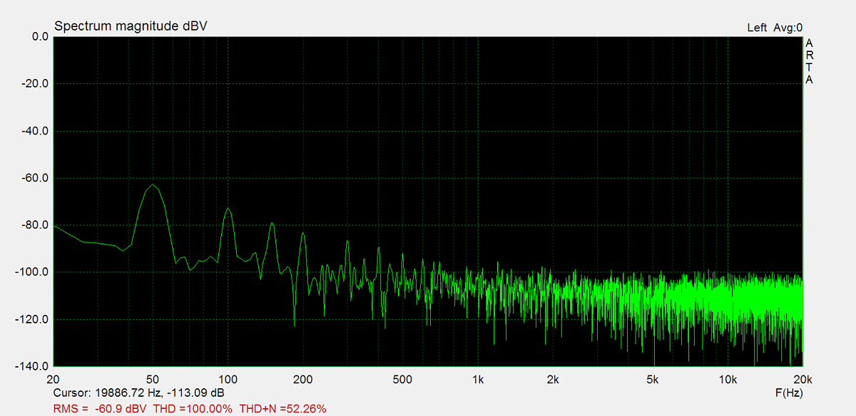
Residual Noise
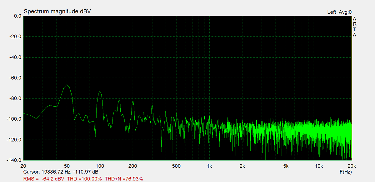
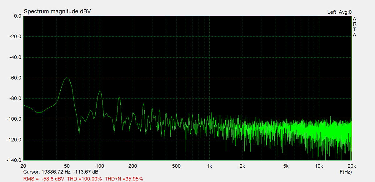
These graphs display the noise levels at various volume positions. To eliminate any interference from the input signal, the input lines are shorted during the measurement. Generally, the noise is highest at the mid-point of the volume range (50%)


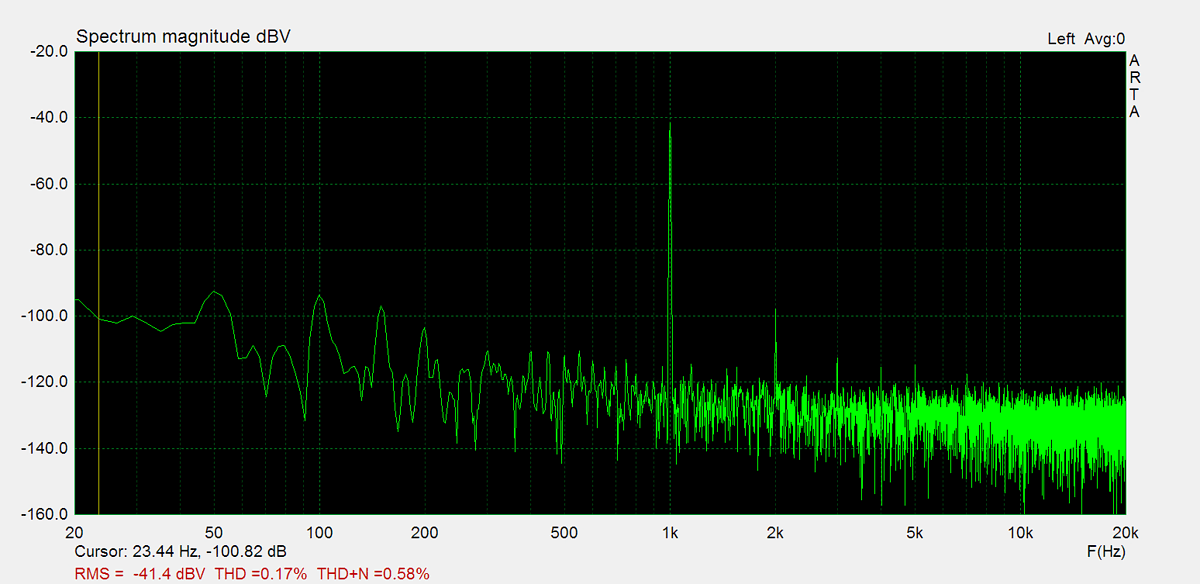
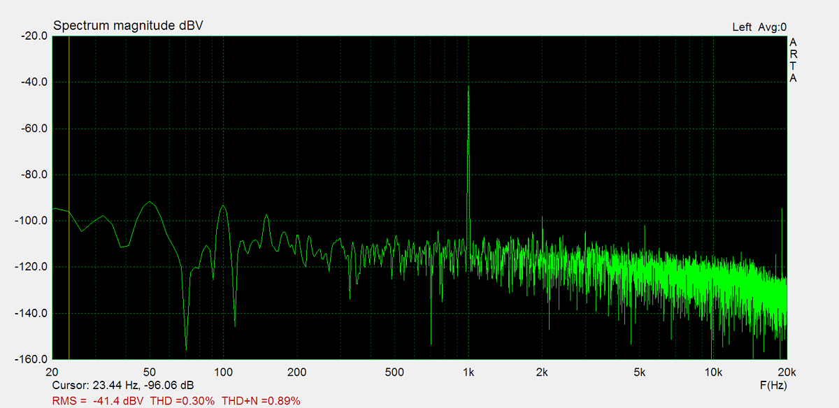
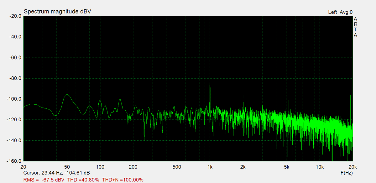
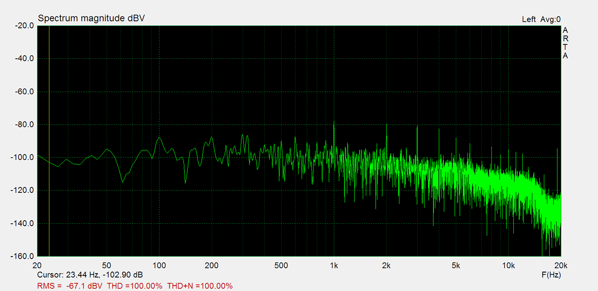
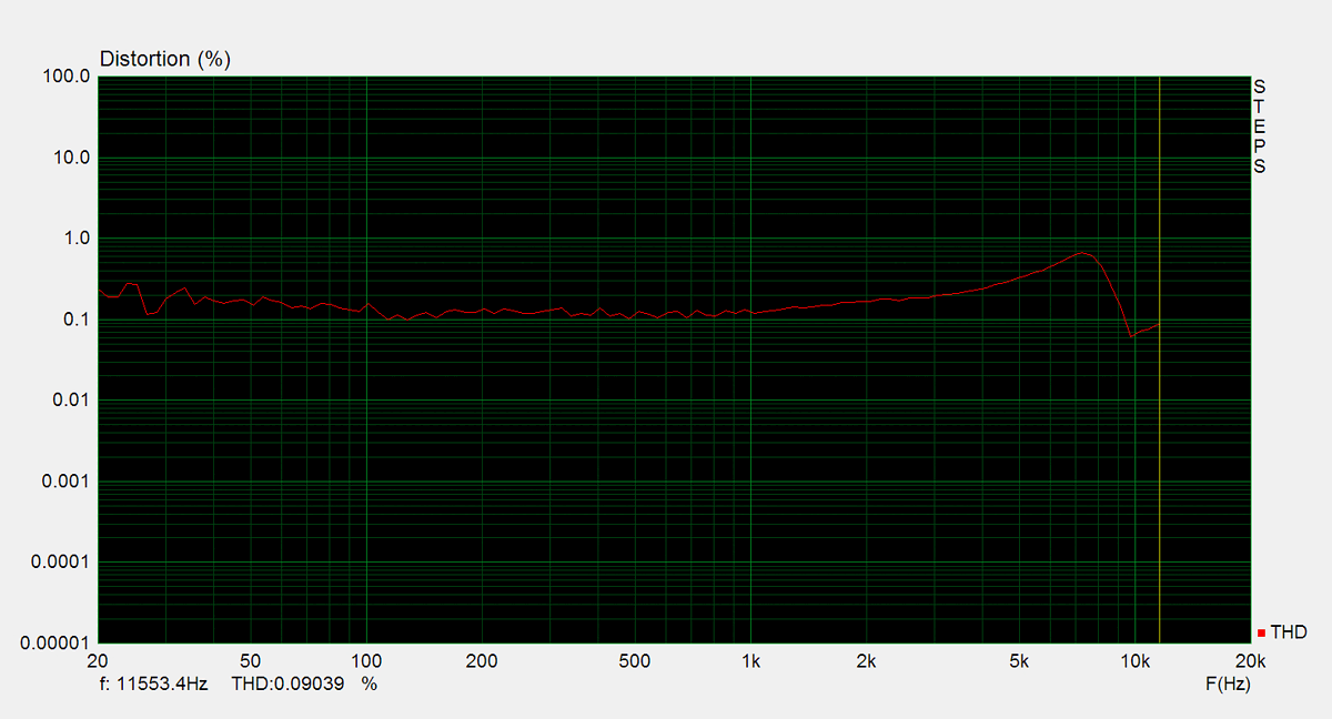
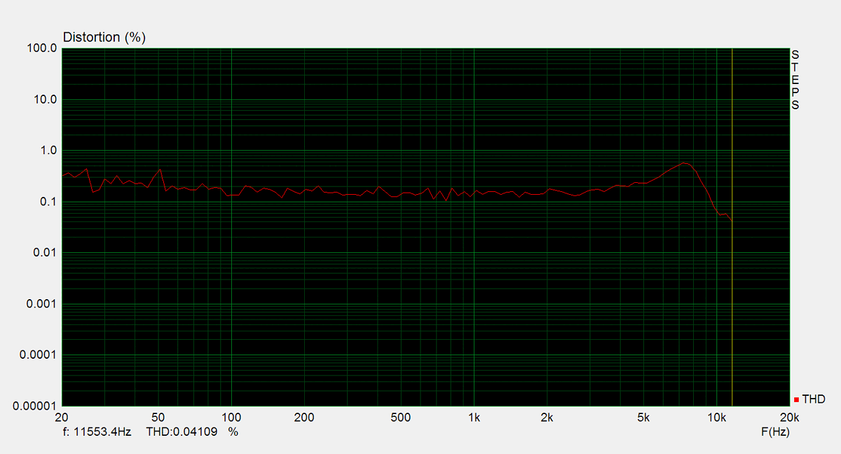
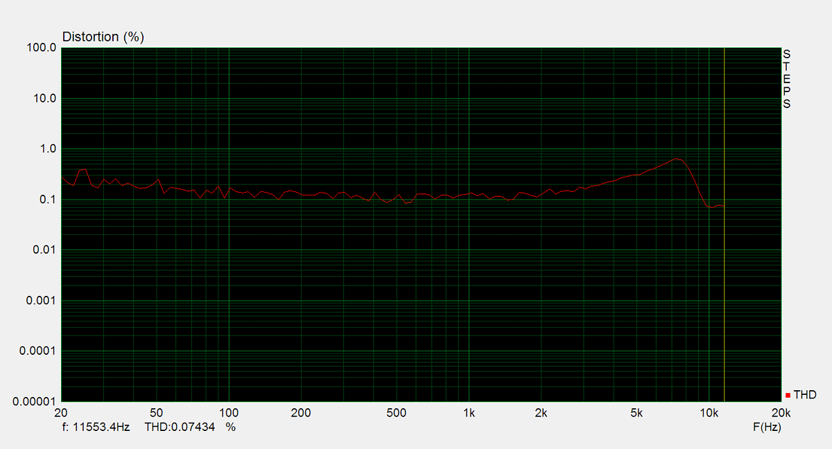
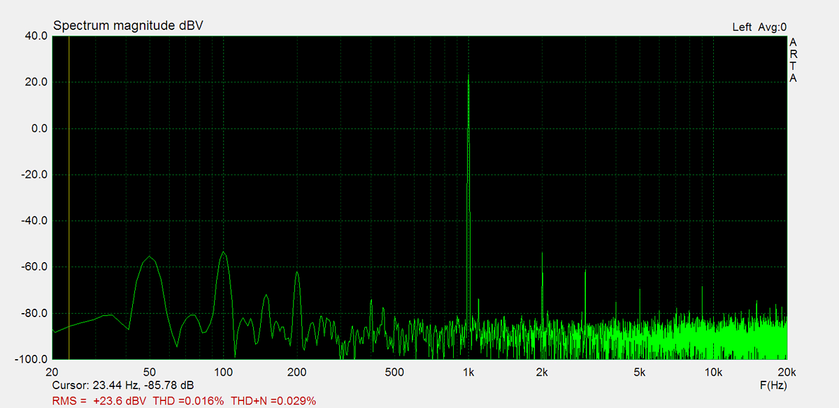
Distorsion
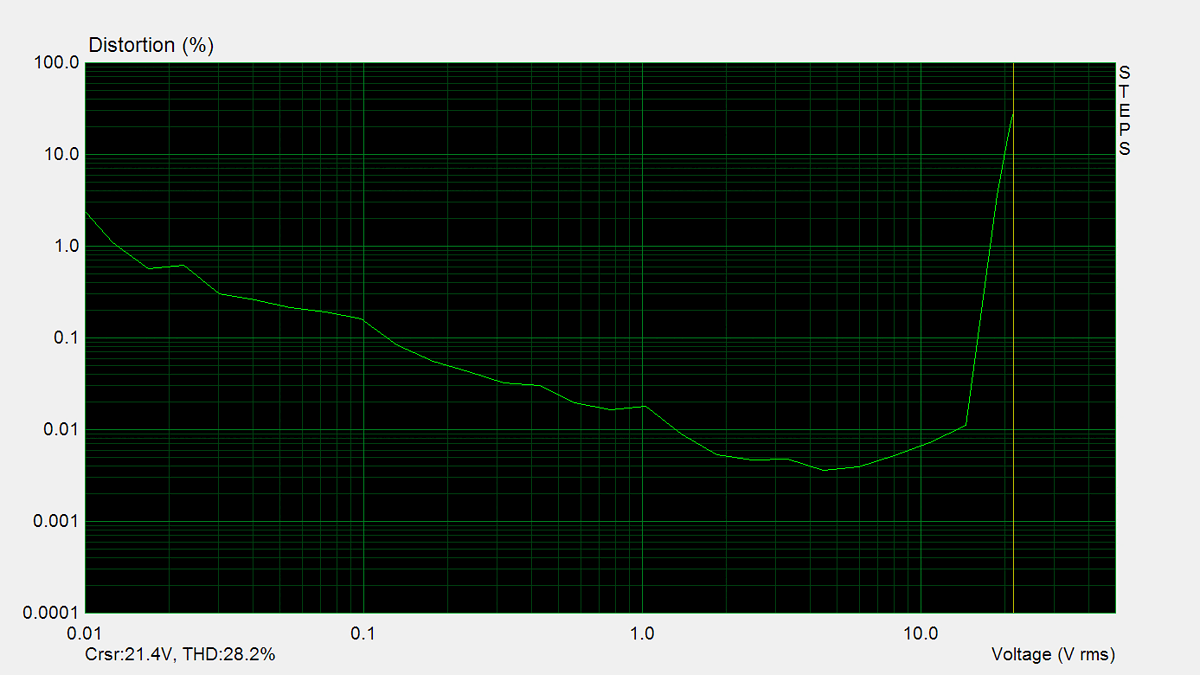
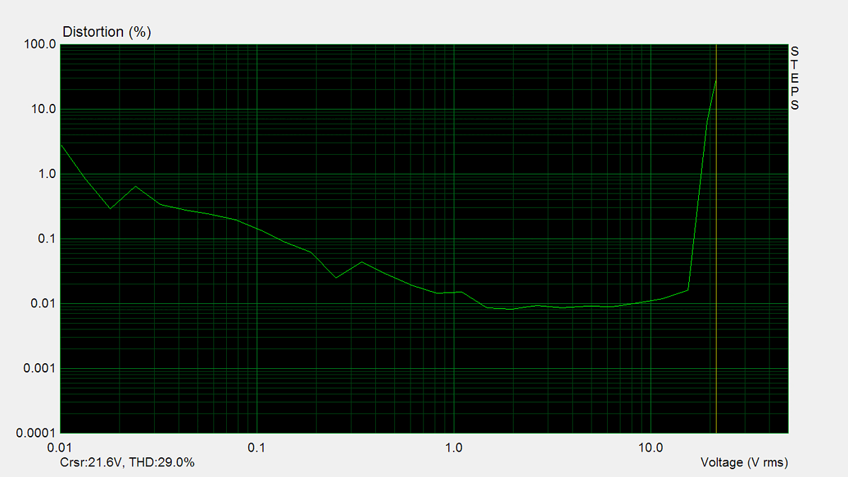
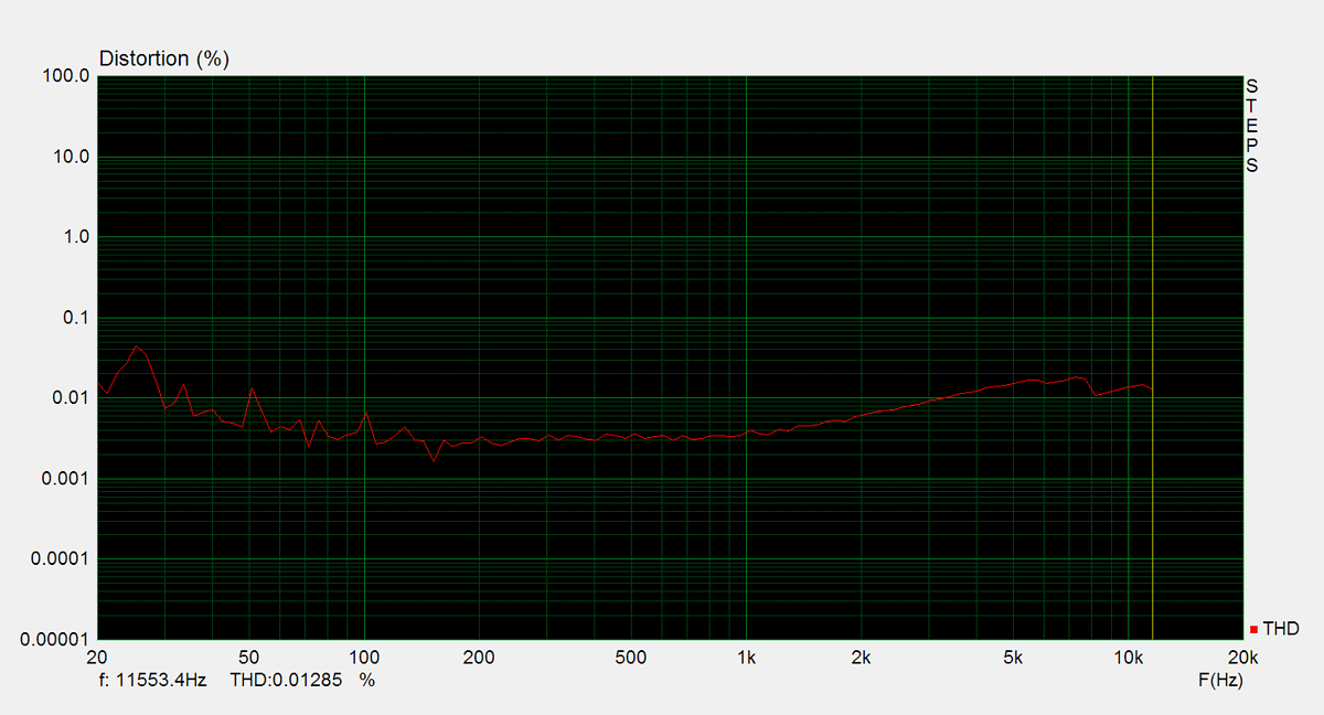
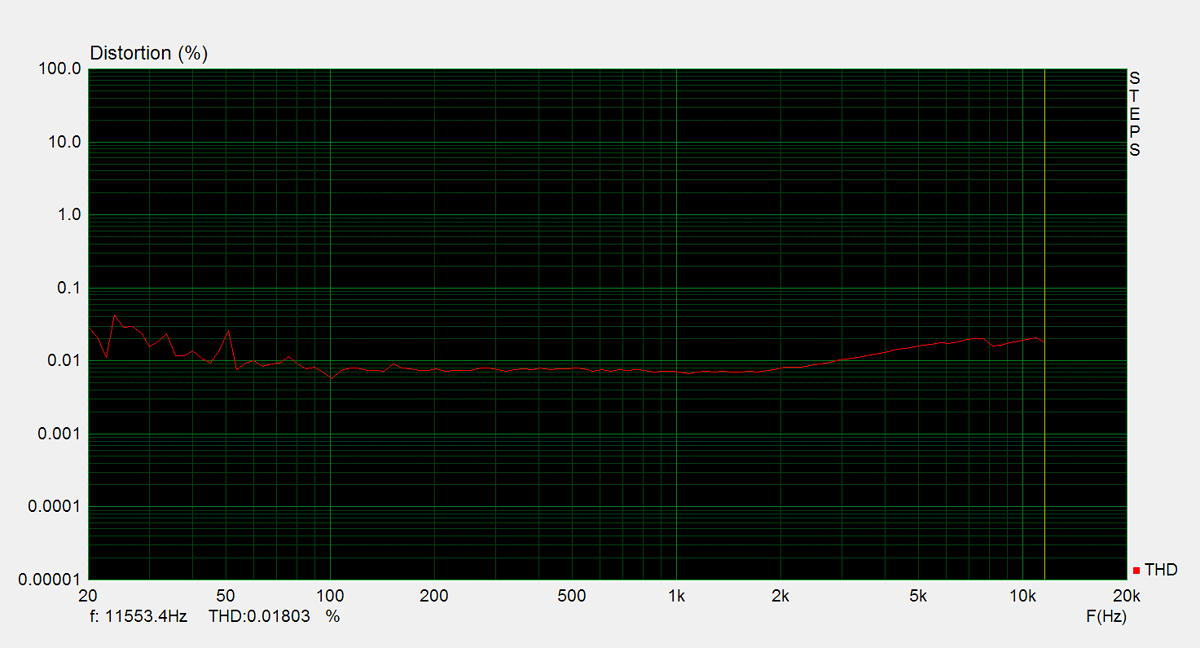
Total harmonic distortion (THD) is measured using a 1kHz sine wave input, with the output level adjusted to meet different conditions. Intermodulation distortion (IMD) is measured using 'two sine' input signal. THD versus voltage is measured with a 1kHz sine wave input, while THD versus frequency is measured at various output levels.

FM Tuner
Measurements of the tuner section were performed using an FM signal generator, with its output fed directly into the antenna input. AM measurements were not conducted.