Tandberg TR 2075
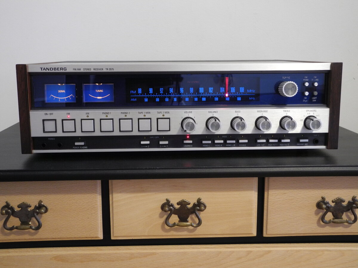
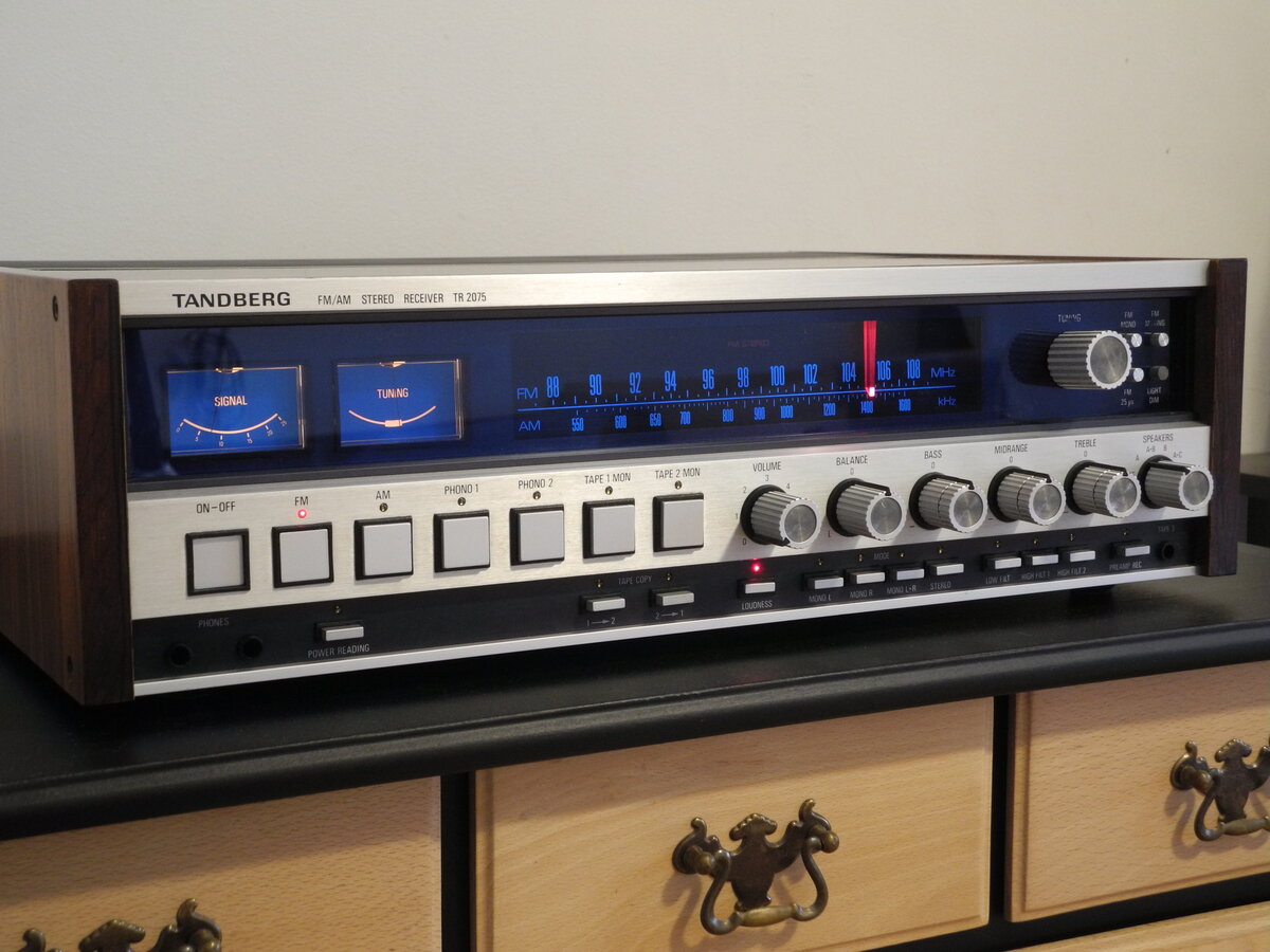
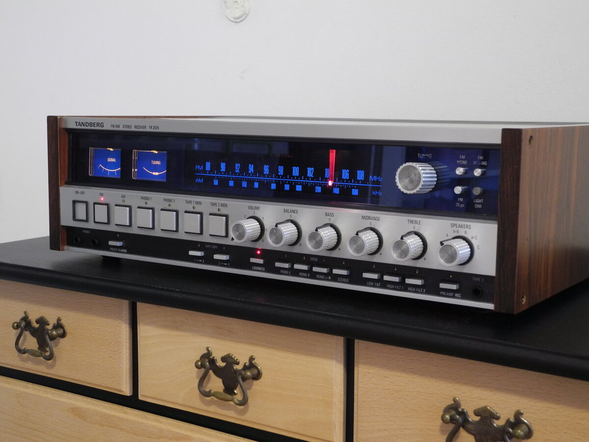
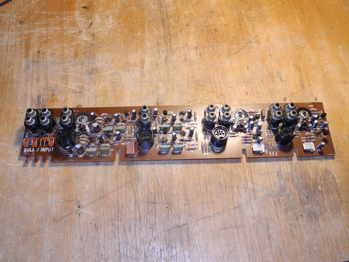
The Tandberg TR 2075 is a high-end stereo receiver from the mid-1970s and represents one of the top models in Tandberg's lineup of that era.
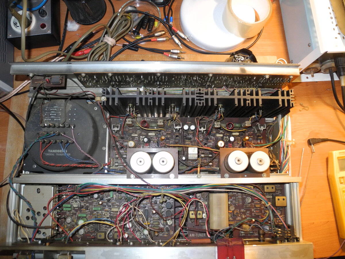
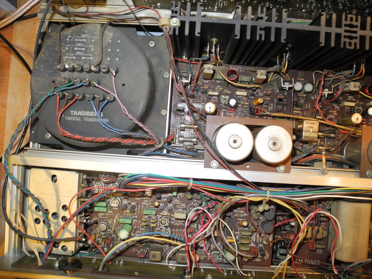
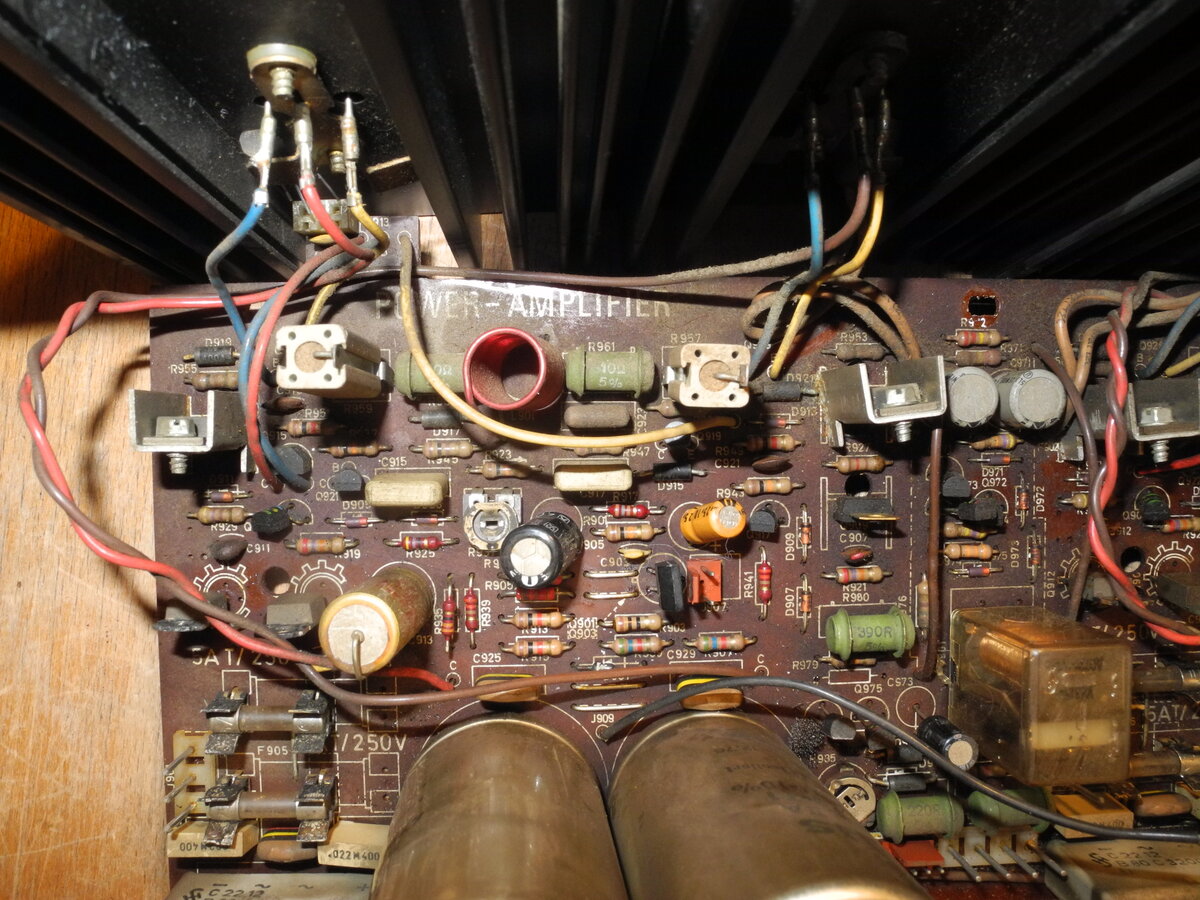
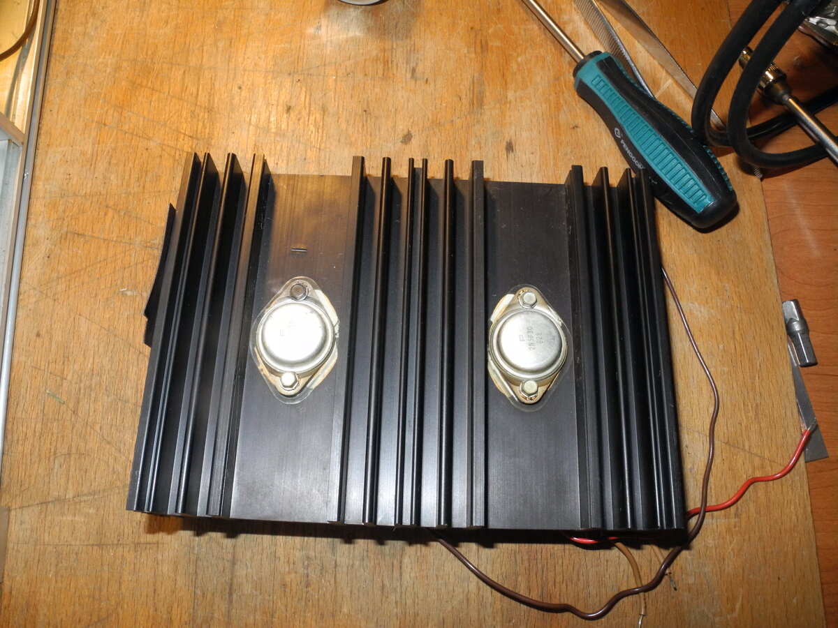
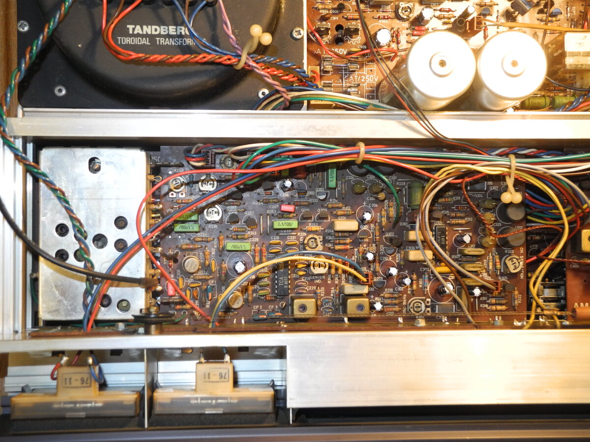
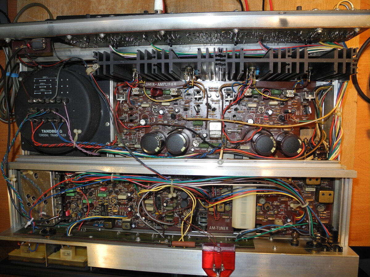
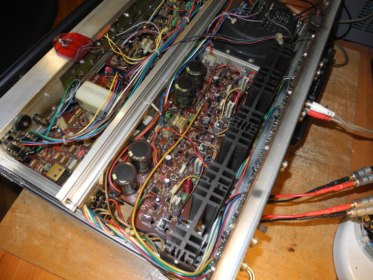
It features a robust internal design with a toroidal power transformer and a dual power supply configuration, using a pair of 4700µF filter capacitors for each channel. The power amplifier is based on complementary 2N5630 and 2N6030 output transistors, arranged in a push-pull emitter follower configuration. This design contributes to stable operation and efficient power delivery.
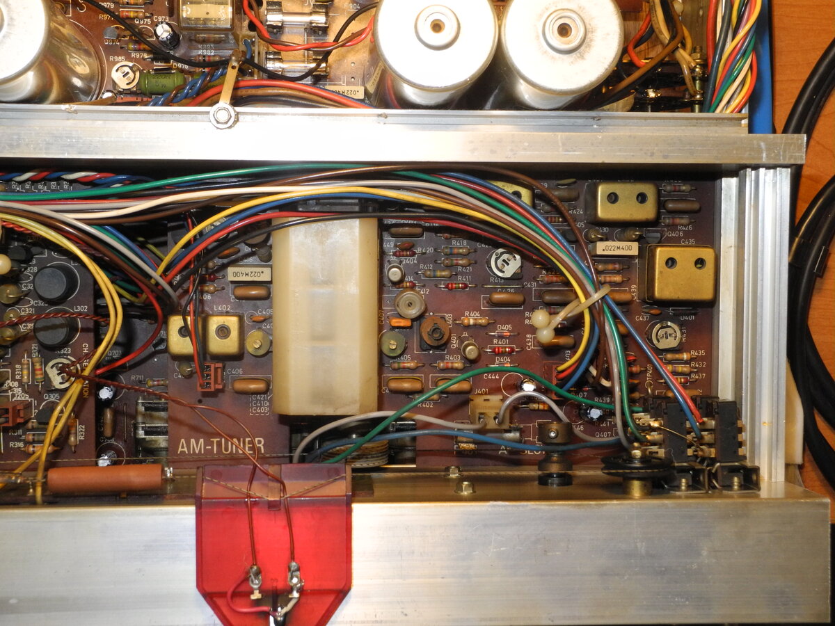
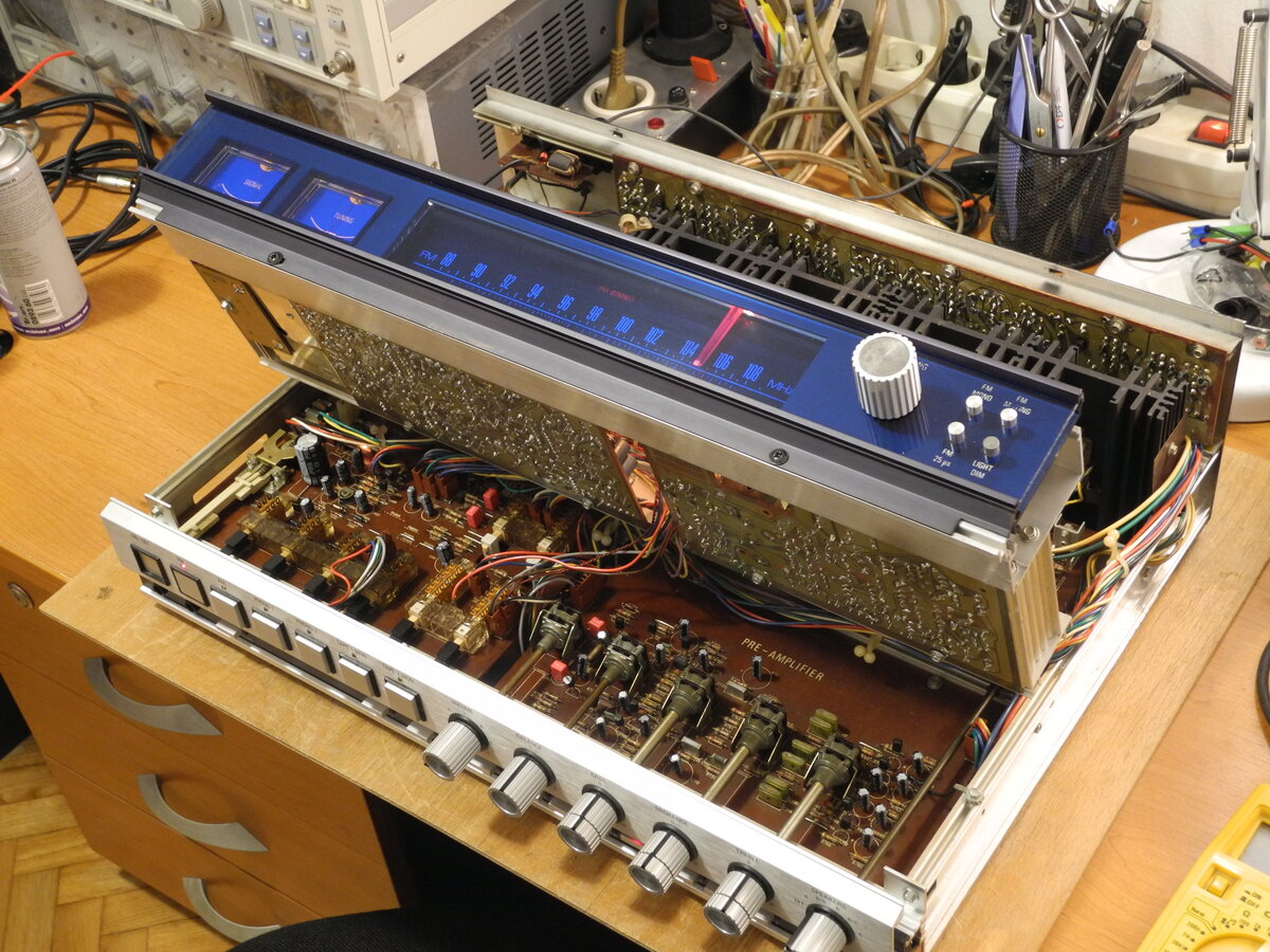
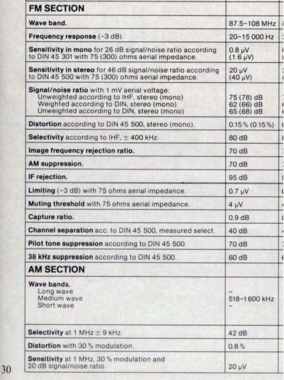
The FM tuner employs four varicap diodes for electronic tuning and uses CA3089 and MC1310 ICs, providing excellent reception and selectivity.
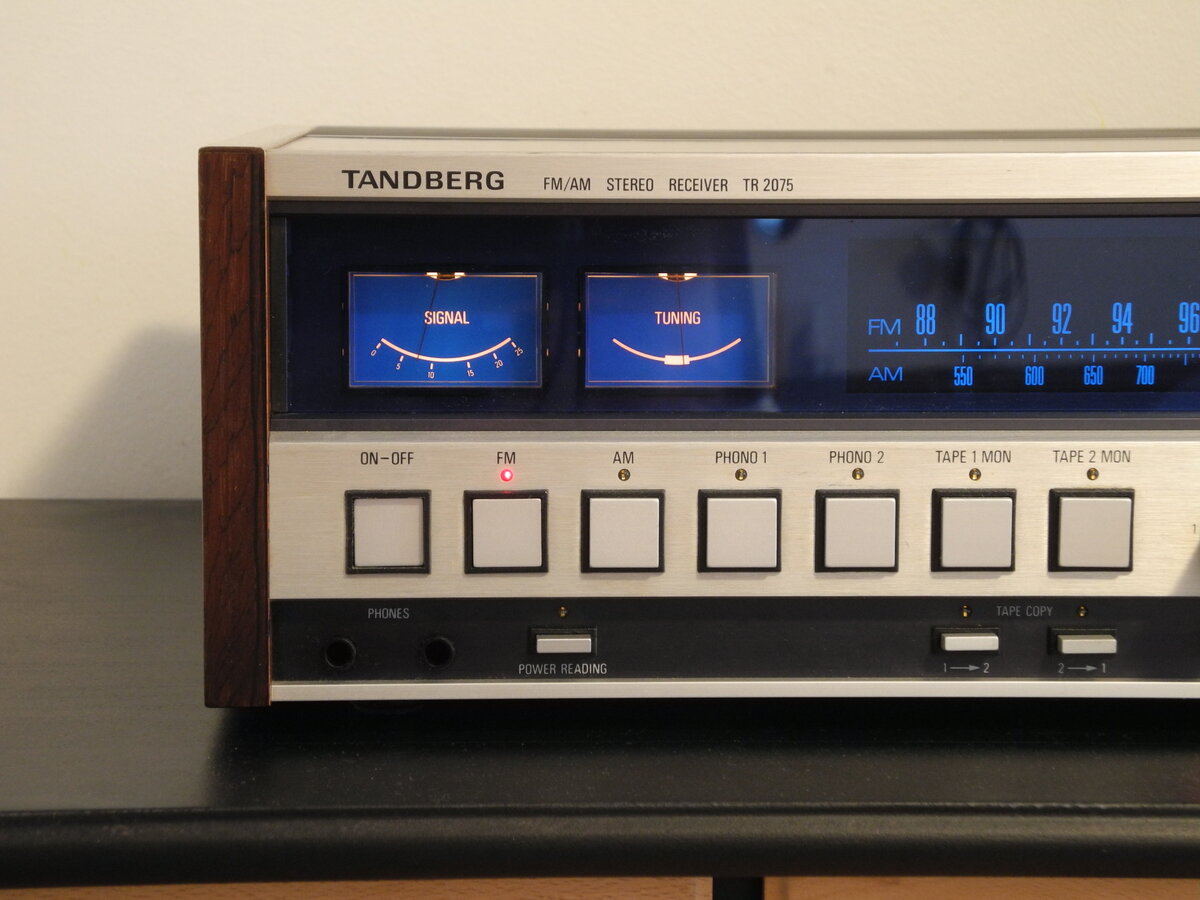
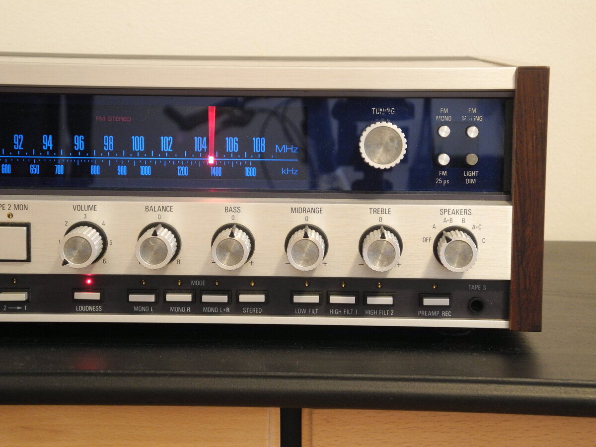
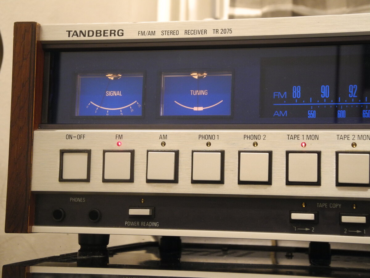
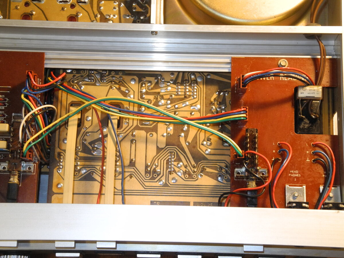
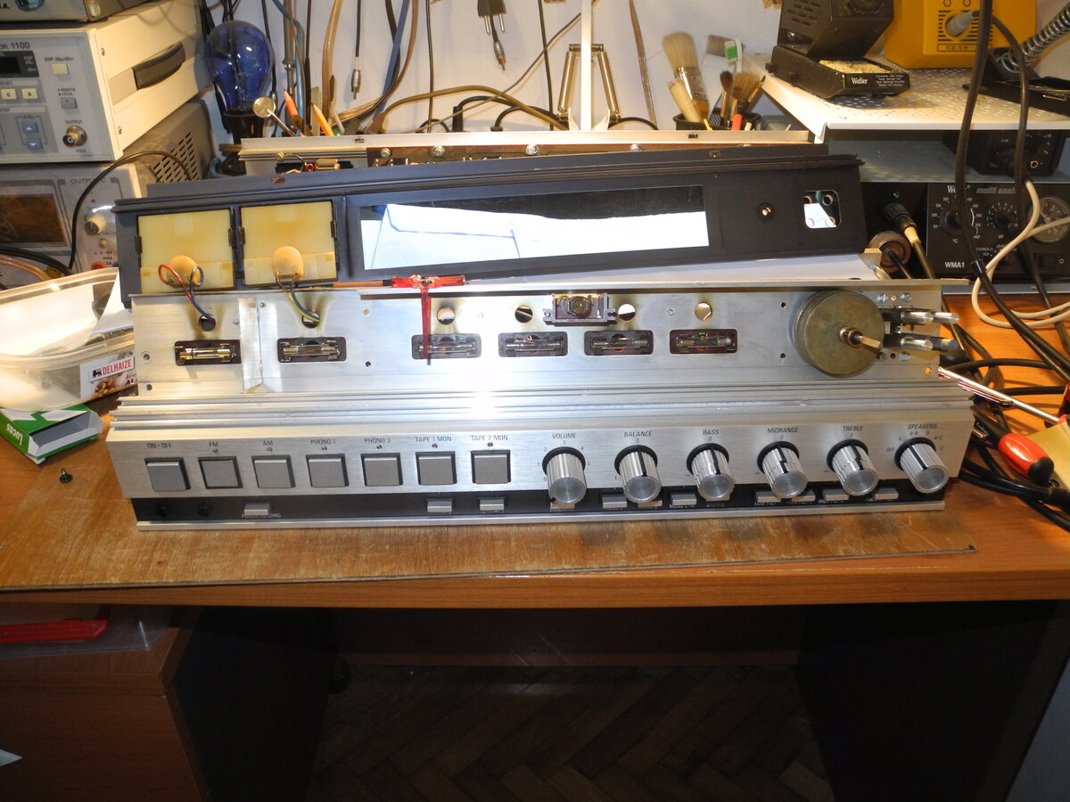
The front panel features a Tandberg-specific combination of square push buttons and round controls, finished in a silver and black design with a blue dial scale.
The sound is full, with strong bass and rich detail. It is no wonder that Tandberg has so many admirers.
Manufacturer: Tandberg
Status: Defunct company
Source: Wikipedia (Tandberg)
General Specifications
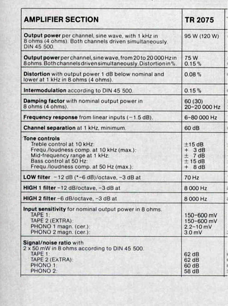
Maximum power (8Ω): 75WFrequency response (-1.5dB): 6Hz-80kHz
THD: 0.08%
IMD: 0.15%
Channel separation: 60dB
Signal to noise ratio (Tape): 62dB
Signal to noise ratio (Phono): 60dB
Input sensitivity (Tape): 150-600mV
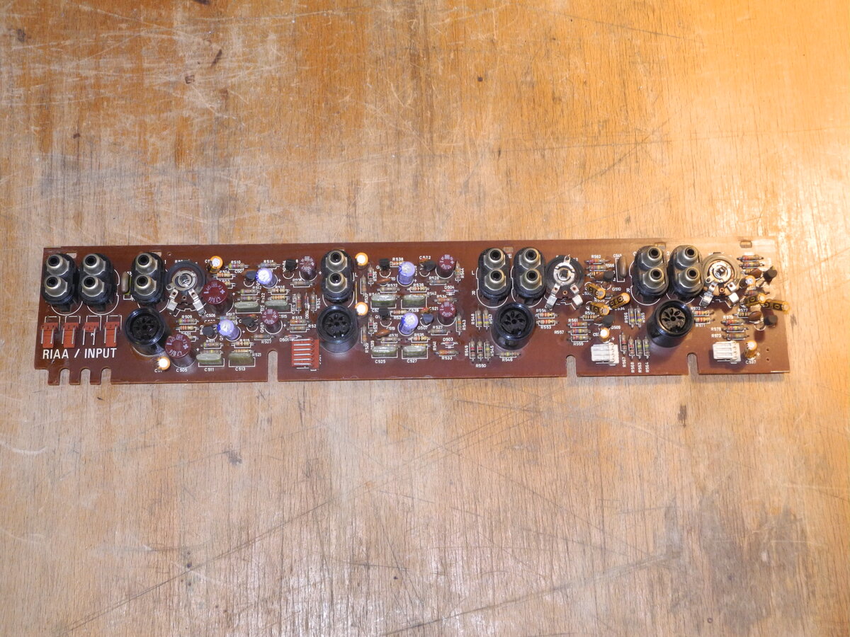
Input sensitivity (Phono): 2.2-10mV
Damping factor: 60
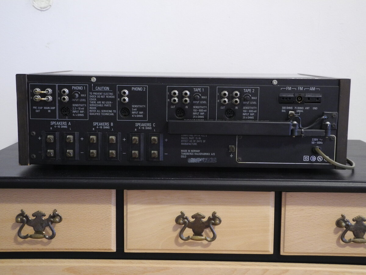
Speaker load impedance: 4Ω-16Ω
Dimensions (WHD): 515×153×353mm
Weight: 12.5kg
Produced: 1974-1977
Initial price: 2700DM
Measured Values
Maximum power (8Ω): 88WFrequency response (20Hz-20kHz): <1.0dB
Channel imbalance: <0.5dB
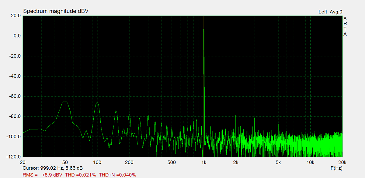
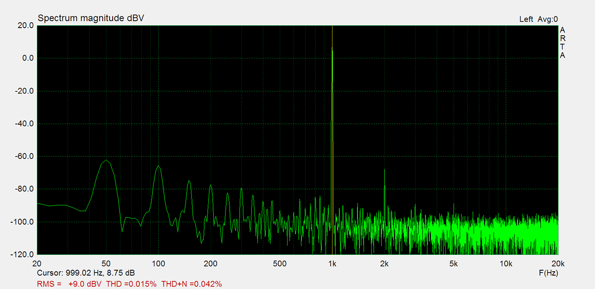
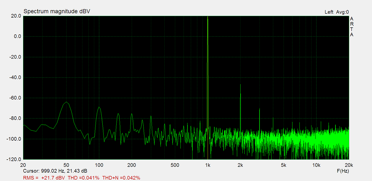
THD (1kHz, 1W): 0.021%
THD+N (1kHz, 1W): 0.042%
THD (1kHz, 10W): 0.0058%
THD+N (1kHz, 10W): 0.059%
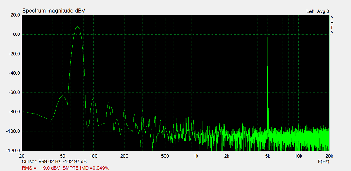
IMD (70Hz, 5kHz, 1W): 0.059%
Noise: -59.6dB
Amplification: 160.0
DC offset L: -1.0mV
DC offset R: 1.5mV
Factory Specification Sheet
Factory specification images are sourced directly from the device's original service manual or user manual. These documents are produced by the manufacturer and provide authoritative information on the product's specifications.
Maximum Power
Maximum power is measured using 8Ω resistors on both channels. A 1kHz sine wave input signal is applied and gradually increased until higher harmonics rise significantly. Typically, this is the point at which output clipping occurs.
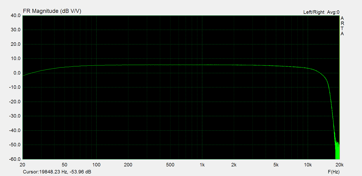
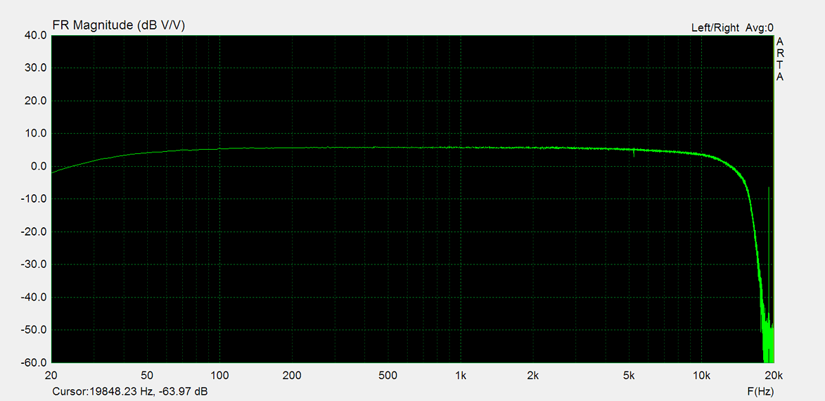
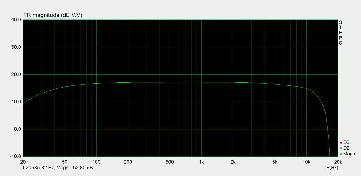
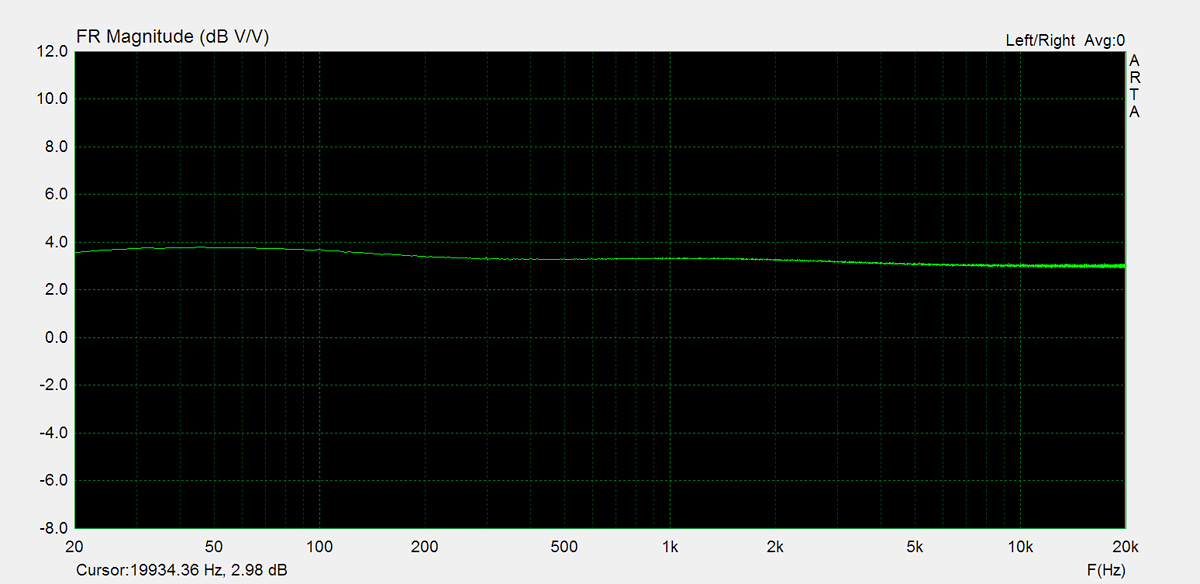
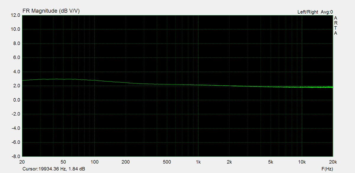
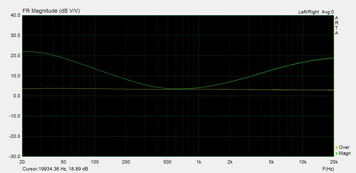
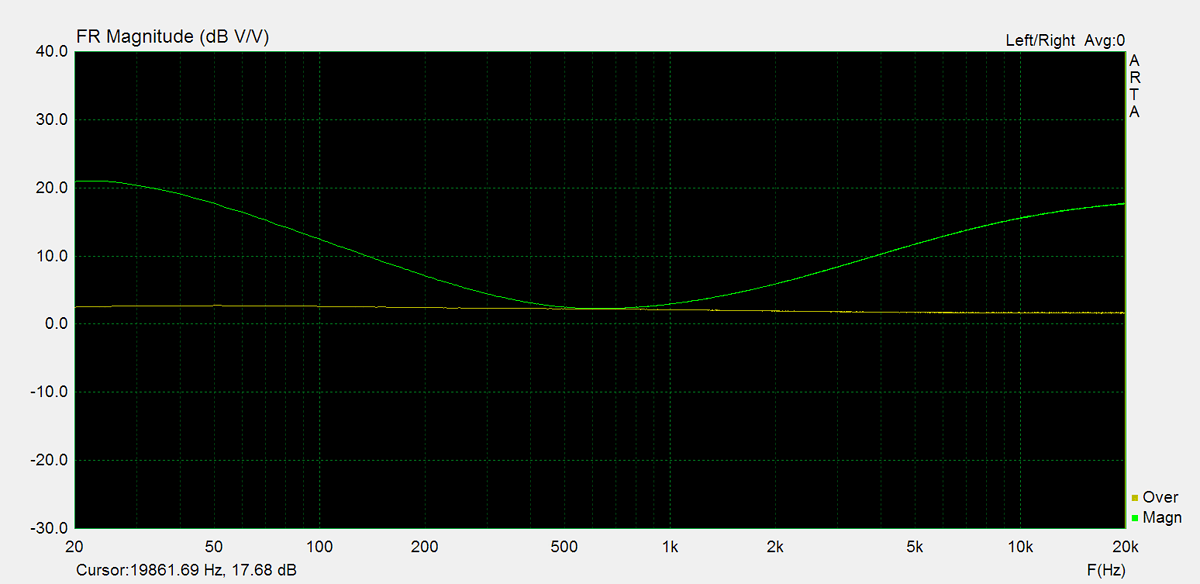
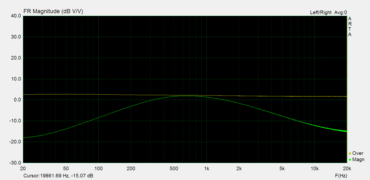
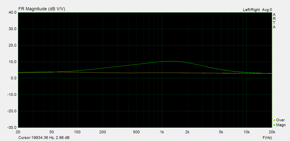
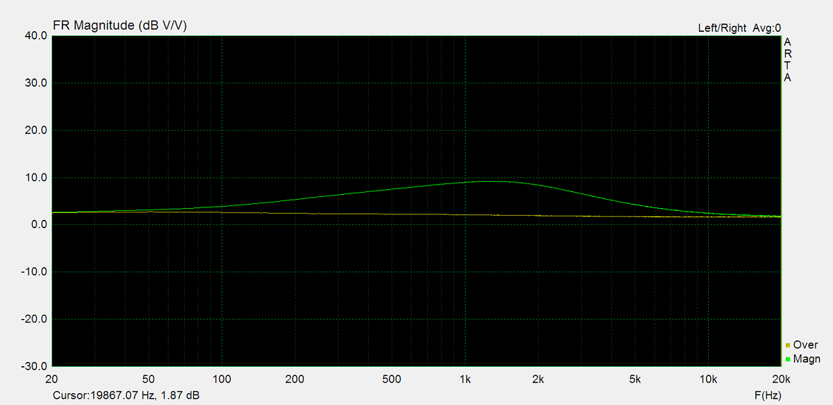
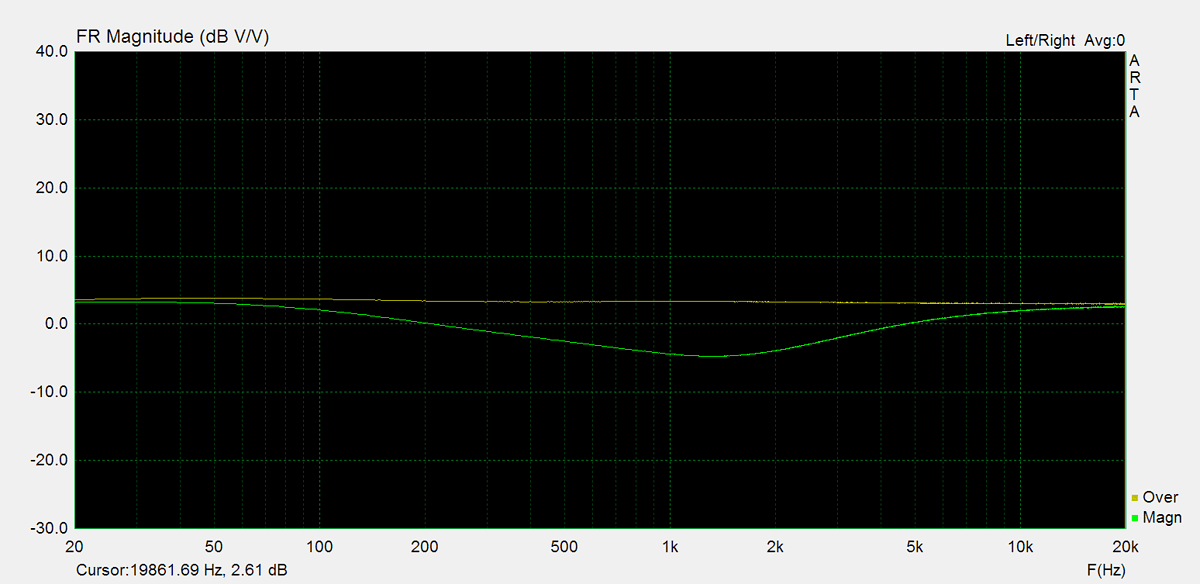
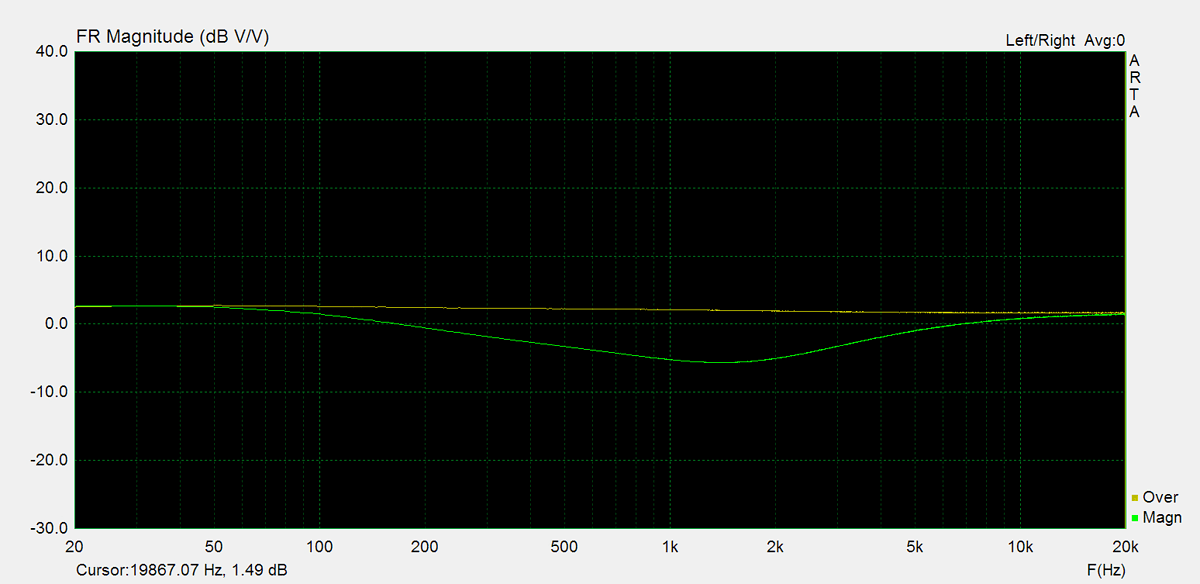
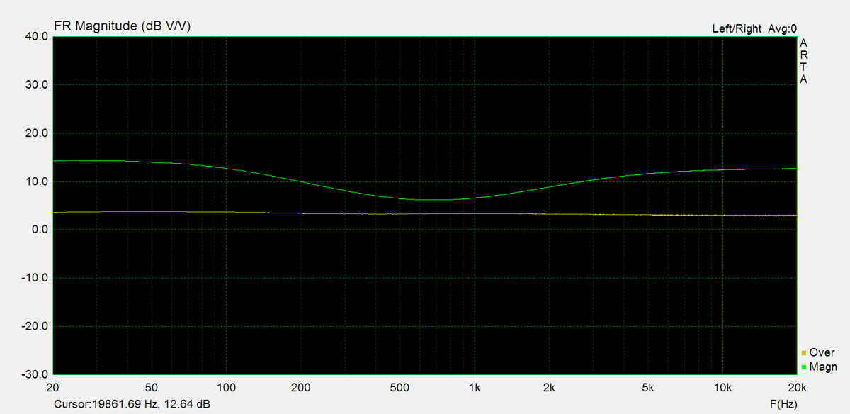
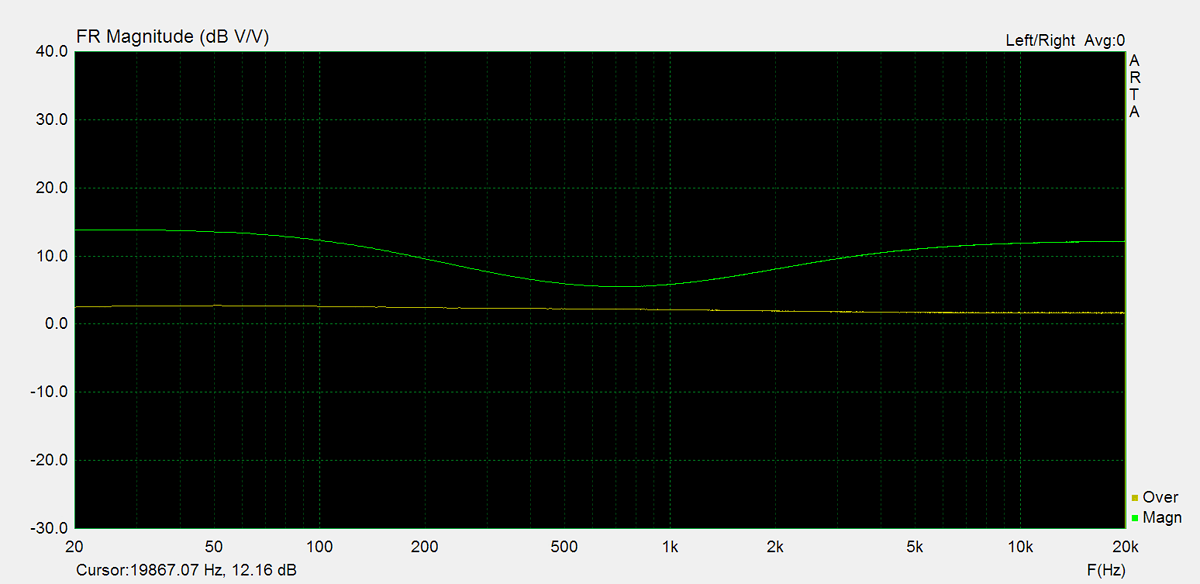
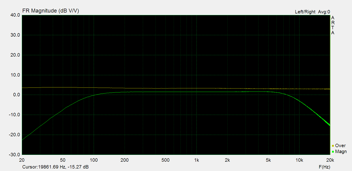
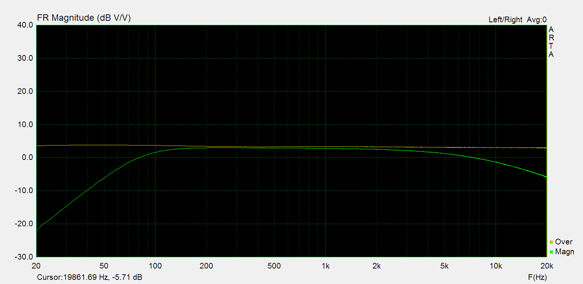
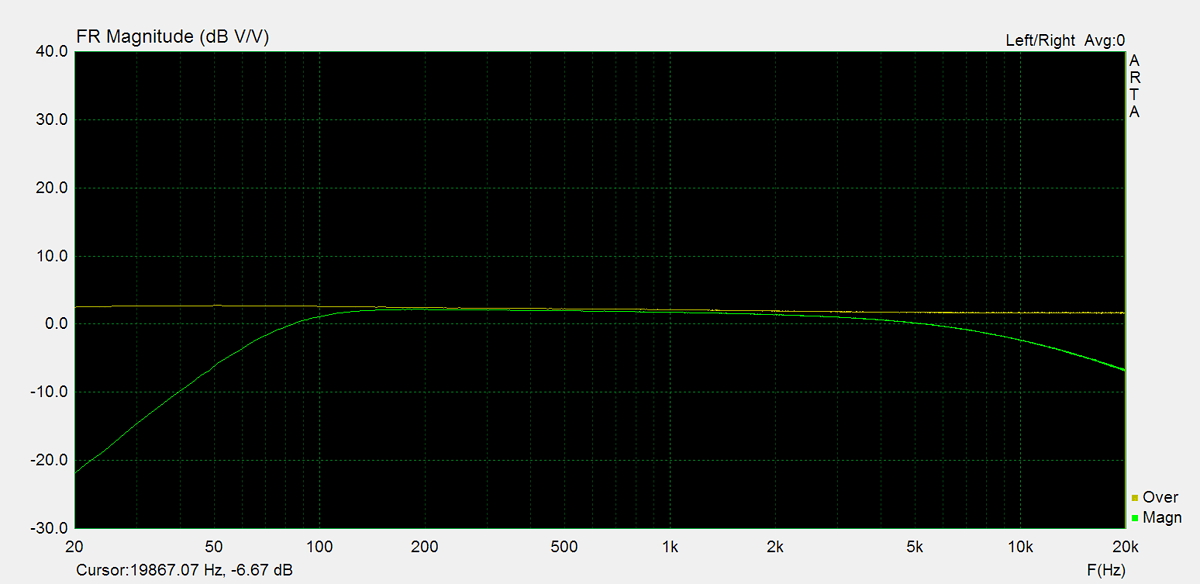
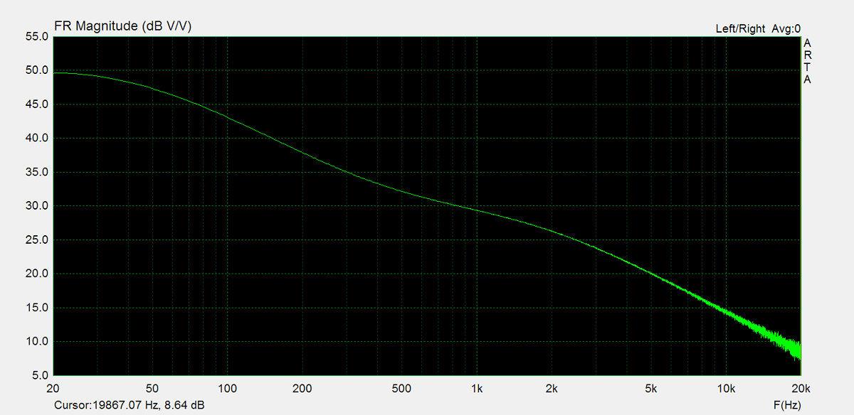
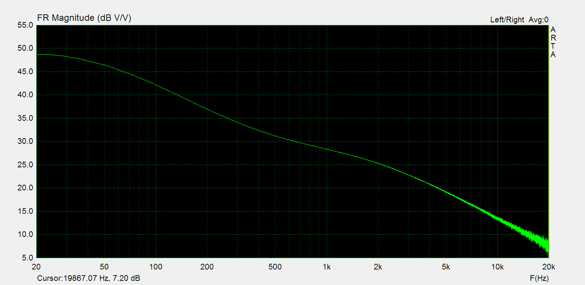
Frequency Response
Frequency response is measured using several equilizer settings. 'Flat' indicates the tone controls are either turned off or set to their neutral position. 'Max' and 'Min' refer to the maximum and minimum tone control positions, respectively. In the phono section, the expected response follows the RIAA equalization curve.


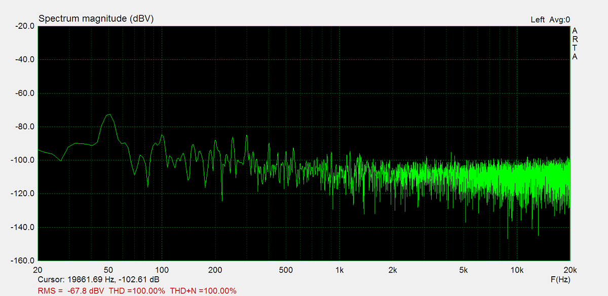
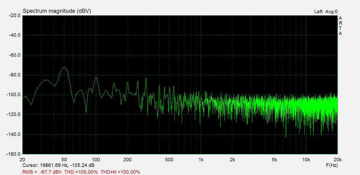
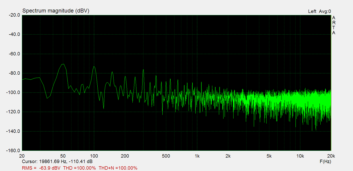
Residual Noise
These graphs display the noise levels at various volume positions. To eliminate any interference from the input signal, the input lines are shorted during the measurement. Generally, the noise is highest at the mid-point of the volume range (50%)


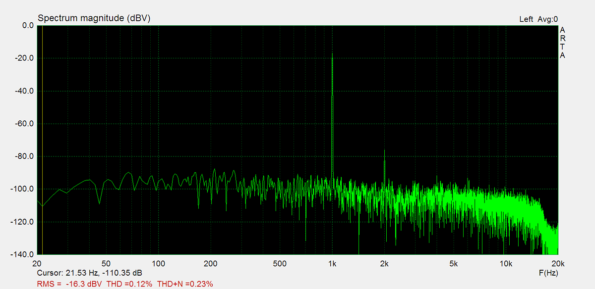
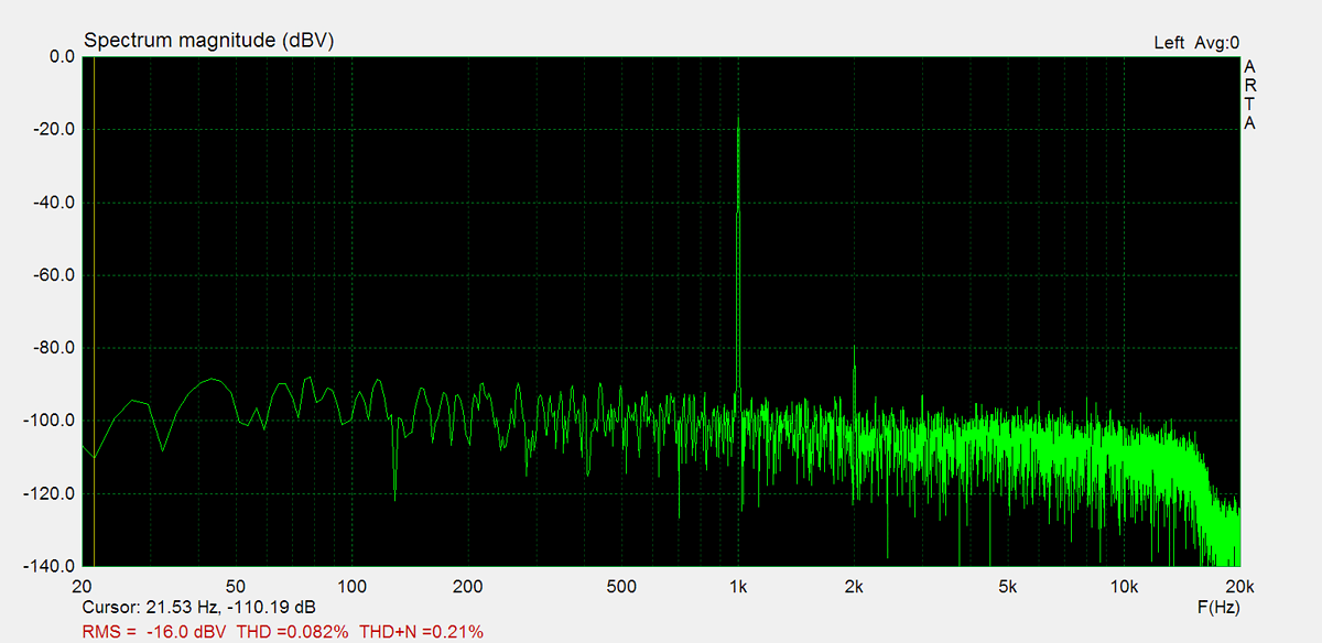
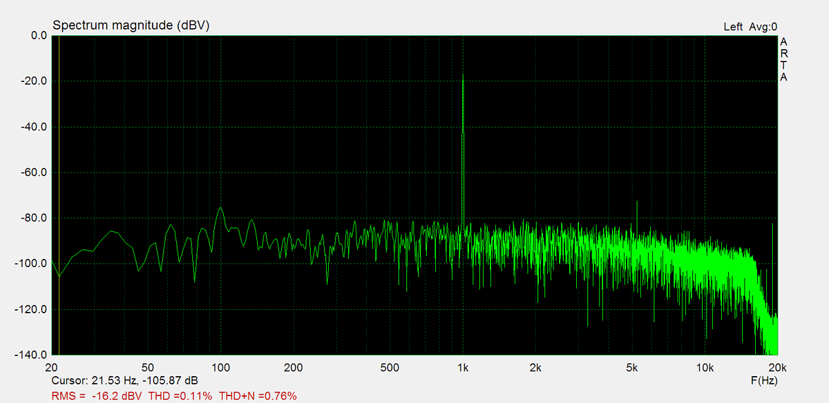
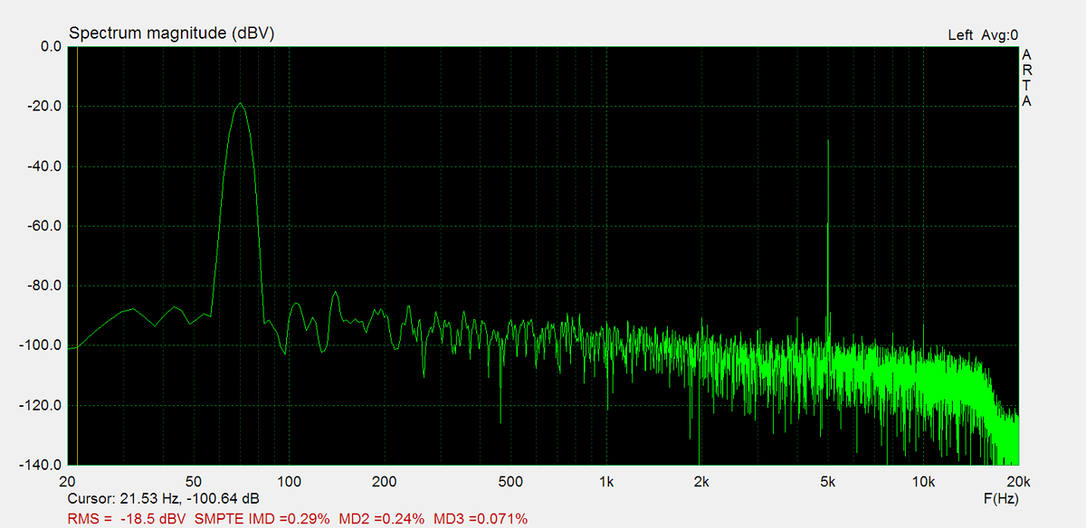
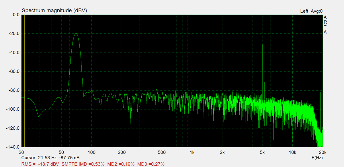
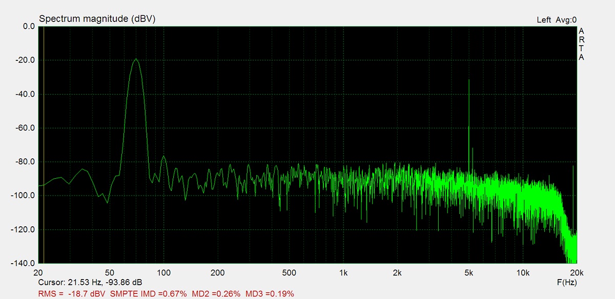
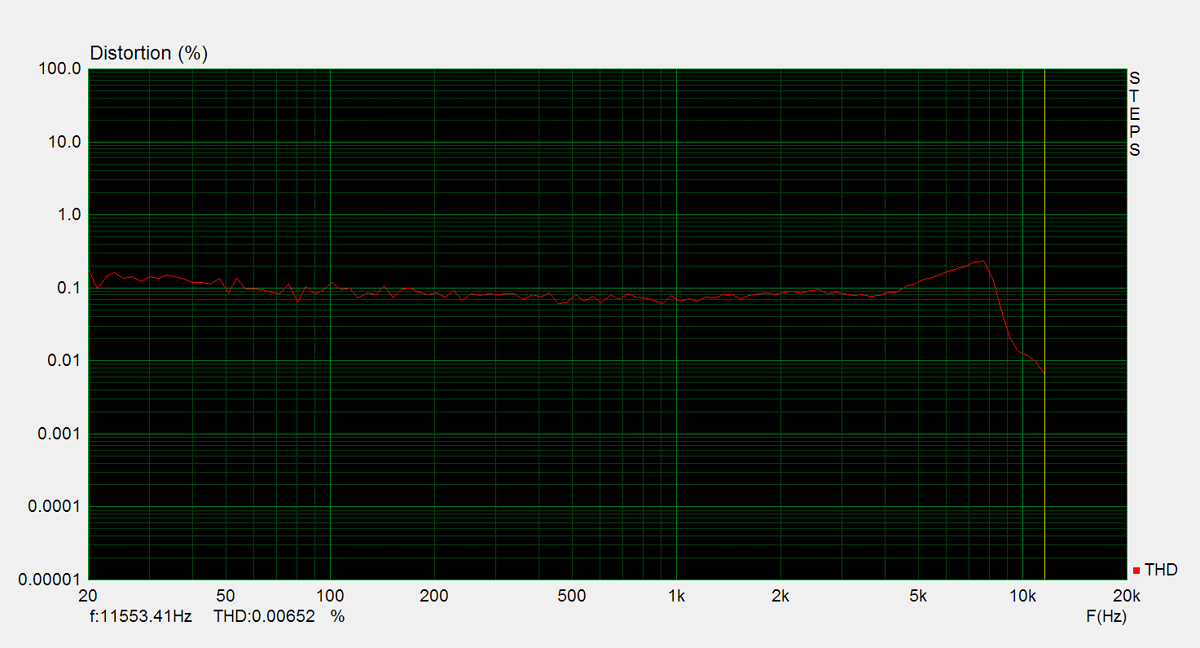
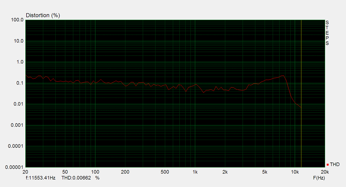
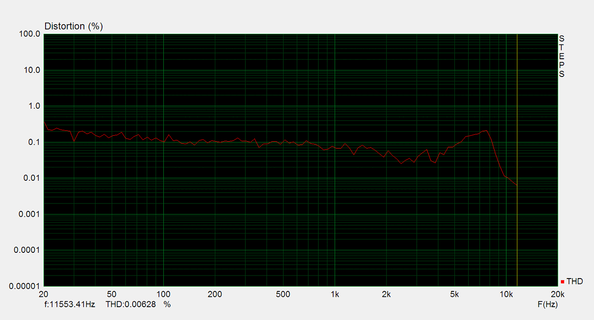
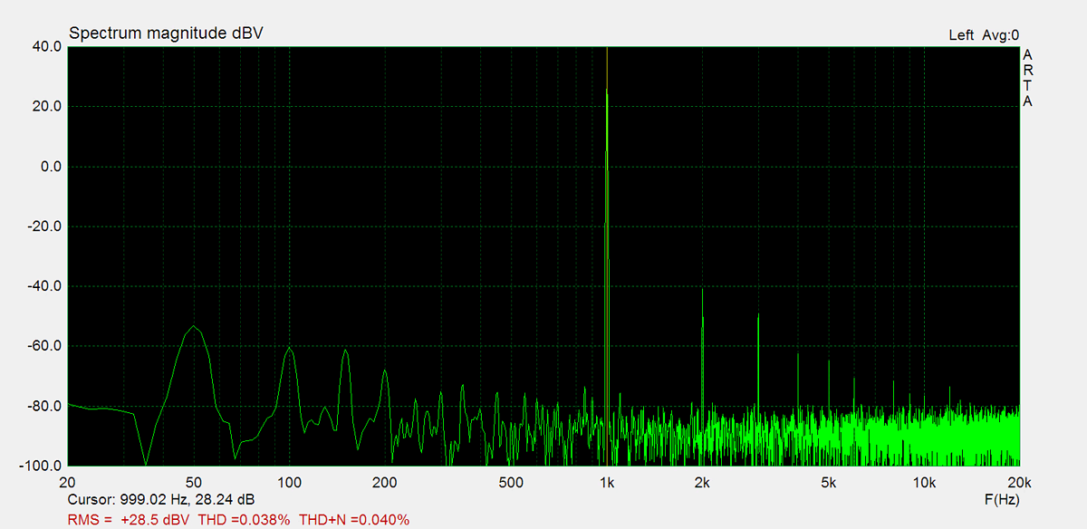
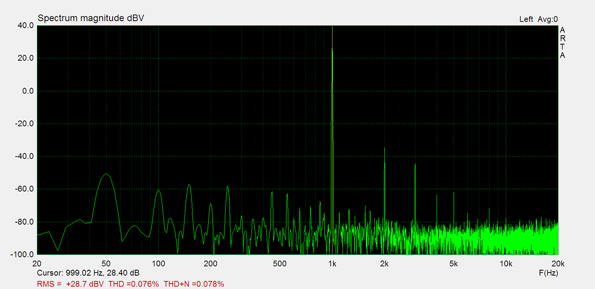
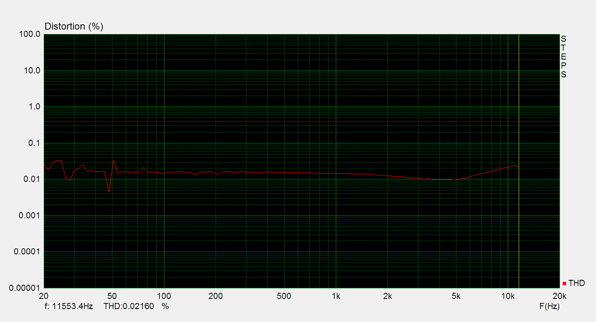
Distorsion
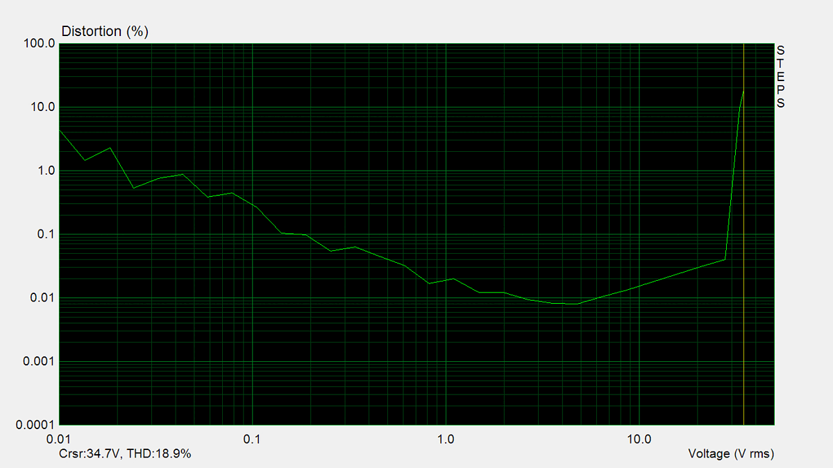
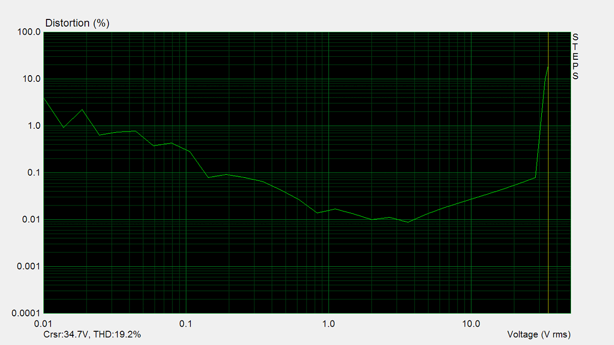
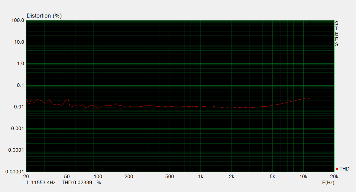
Total harmonic distortion (THD) is measured using a 1kHz sine wave input, with the output level adjusted to meet different conditions. Intermodulation distortion (IMD) is measured using 'two sine' input signal. THD versus voltage is measured with a 1kHz sine wave input, while THD versus frequency is measured at various output levels.


FM Tuner
Measurements of the tuner section were performed using an FM signal generator, with its output fed directly into the antenna input. AM measurements were not conducted.